Radio W4KAZ Thanks for stopping by the virtual KazShack. Feel free to comment - I often approve them.
|
By w4kaz, created on 2021.03.17 at 08:22:00 | last changed on 2021.05.06 at 22:33:20 |
The “Tune-up-ening”
The first attempts to tune up the real antenna did not go well. I found from the trap dipole project attaching the wires beyond the trap was needed to get the higher bands tuned properly. This worked against me here. With the high impedance on the end fed I was better off tuning the 40m antenna segment without the coil and 80m tail attached. Unfortunately, I wasted a lot of time experimenting/snipping before I decided to detach the inner antenna from the coil.
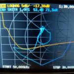
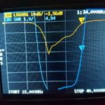
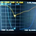
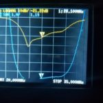
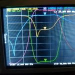
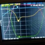
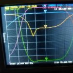
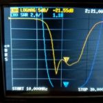
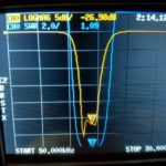
Once taking that step, I found I had probably trimmed too much off. Tuning for 40m without the coil proved simple enough. After that the other bands were easier too. I was also able to re-attach the coil and 80m tail, and find tap settings and tail lengths to allow operation with good matches on 80m and 20m. With the 20m tails attached 40m operation on the upper edge is possible. With tails 40m SWR was a bit high on CW segment, although possible with a tuner. 10m seemed unaffected by the coil and tail. 15m provided low SWR only with the coil and tail detached, but SWR of 2:1 up to 3:1 with 80m coil and tail.
Antenna Stuff
The coil as wound measured out to 77.5uh, resonant at 3.85Mhz with 22pf of capacitance. It is ~63 close-wound turns on a mystery plastic coil form of ~2 inch diameter, wound with 16ga solid insulated wire. The final wire length in the 40m section is xxft(zz.zm). The 80m tail is xxft(zz.zzm) in length and the portion for ssb(75m) is xxft(zz.zm). To make the choices more flexible for POTA or other portable uses, I have a series of jumpers in several key places.
The first of the jumpers is installed near the feed point. The antenna was trimmed at the feed point for ease-of-access reasons. Since I ultimately decided I had over-trimmed before detaching the 80m coil&tail, it seemed easier to insert a jumper there. This will also allow having an easy method of re-tuning on the fly if it seems necessary in different deployment configurations.Â
The next set of jumpers comes at the junction between the 40m antenna and the 80m coil&tail. There are two more jumpers on the 80m tail itself, positioned to allow choosing between a mid-band SSB section centered at around 3.8Mhz or a CW section centered at about 3.575Mhz. The lower section will allow use on both CW and in the lower 3.600Mhz SSB segment.
The antenna can be deployed with or without the 80m coil&tail. I found that the matches in the 40m and higher segments are much with the tail removed/detached.Â
All Taps NOT Ideal
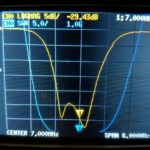
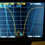
As described in previous posts, the transformer brewed up for this project has multiple taps, not the fashionable 49:1 single solution. It turned out having the choices of taps gave better SWR matches than any single tap. In fact, only one of the taps worked well for the 15m/10m bands, the lowest impedance 4.5:1 tap. For 40m and 80m, the 8.5:1 tap proved the best choice. 20m SWR curves favored the 7.5:1 tap, although the 6.5:1 tap proved useful with the 80m cw configuration. When configured for 80m CW the 6.5:1 tap provides better than a 1.5:1 SWR across all of 20m. Â
TAP Cheat Sheet
Taps 40m and up, bare wire, NO 80m coil&tail
| BAND |
TAP |
Best SWR |
 SWR range to expect |
| 40m |
8.5:1 |
7.15Mhz@ 1.2:1swr |
Entire band, 1.8:1 up to 2:1Â centered on 7.15 |
| 20m_1 |
7.5:1 |
14.15 |
Entire band good favoring CW section |
| 20m_2 |
6.5:1 |
14.275 |
Entire band good favoring SSB section |
| 15m |
4.5:1 |
21.3 |
Entire band under 2:1 |
| 10m |
4.5:1 |
28.2 |
28.00 thru 28.800 under 2:1 |
Taps with 80m SSB section
| BAND |
TAP |
Best SWR |
 SWR range to expect |
| 80m |
8.5:1 |
3.825Mhz@ 1.2:1swr |
3.7 thru 3.9Mhz , ?tuner at edges? |
| 40m |
8.5:1 |
7.3Mhz, 2:1 |
7.2 to 7.3Mhz, tuner needed |
| 20m_1 |
7.5:1 |
14.1 |
14 to 14.35 under 2:1 |
| 20m_2 |
6.5:1 |
14.225 |
Best choice, entire band good favoring SSB section |
| 15m |
4.5:1 |
21.05 @ 2:1 |
21.0 to 21.35, SWR over 3:1 above 21.35 |
| 10m |
4.5:1 |
28.2 |
28.00 thru 28.800 under 2:1 |
Taps with 80m CW section
| BAND |
TAP |
Best SWR |
SWR Range to expect |
| 80m |
8.5:1 |
 |
3.525 to 3.75 <2:1 |
| 40m |
8.5:1 |
 |
7.2 up under 2:1 |
| 40m_2 |
8.5:1 |
1.3:1@7.3 |
40m jumper ins, useable on cw |
| 20m |
7.5:1 |
14.0 |
14 up to 14.275 < 2:1 |
| 20m_2 |
6.5:1 |
1.5 |
40m jumper ins, all band |
| 15m |
4.5:1 |
21.245 @ 2:1 |
 |
| 10m |
4.5:1 |
28.1 |
28.0 to 28.7 < 2:1 |
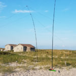
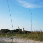
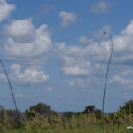
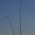
 Test Deploy
All tuning was done with the antenna strung up using two Jackite telescoping poles as supports. A 31 footer is used for the vertical portion, and the feed point is at about 4 feet off the ground. The horizontal runs out about 40 feet to the second mast, a 28 footer. The second mast supports the weight of the wire and the loading coil, probably the heaviest portion of the antenna if used.  I ran a 7 foot long counterpoise wire, and a six foot long coax jumper angles down to ground level from the feedpoint to the first choke, eight turns of coax wound on a ft-240-31 ferrite(another 6 foot jumper for that).Â
The short section of straight coax jumper will likely be a second counterpoise for the antenna. The first choke plugs into a second choke constructed of 10 turns of a 14ga wire pair wound on a second ft-240-31 ferrite and mounted in an enclosure. From the chokes a fifty foot long lmr 240 feedline is attached, and all testing was done at the end of the feedline. That simulates the most likely portable deployment.
FWIW, SWR results did not change when the fifty foot section of coax was removed. Will be a curiosity to find out if altering the shape of the deployed antenna changes SWR.Â
Additionally, I toyed around with inserting pieces of wire as jumpers to lengthen the 40m section. These jumpers are inserted close to the feedpoint on the vertical section. I inserted them to try to improve 40m SWR when the 80m loading coil&tail were linked in, as 40m SWR was too high for CW operation without tuner with tail attached. This turns out to be a useful compromise solution. It will allow using either 40m or 80m without adjustment, and 20m/10m can be used with tap change. 15m is the odd man out in this configuration, but could maybe be used with a tuner.
Stress Test Awaiting
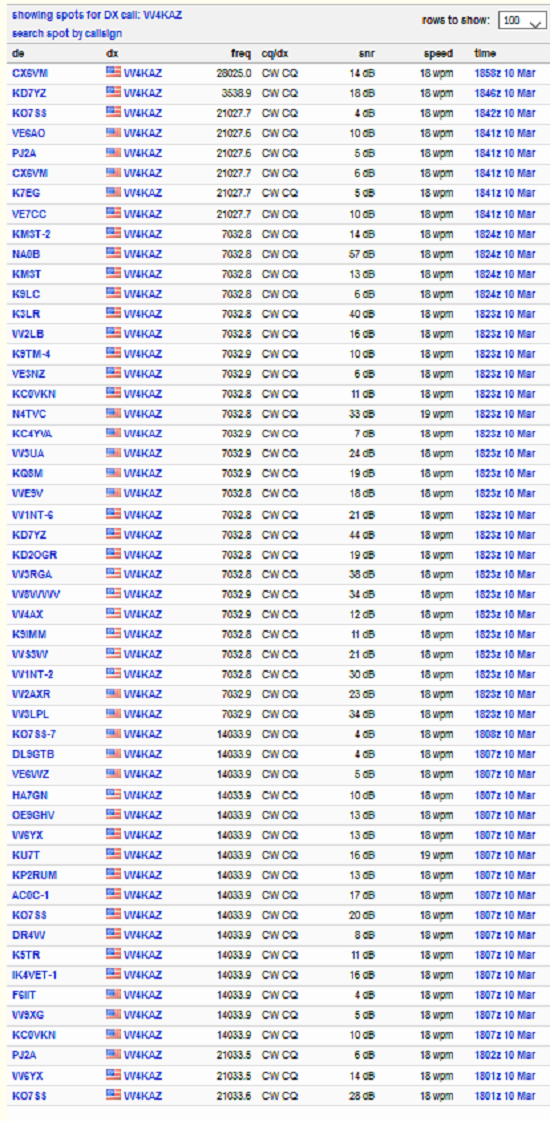
Following are some key down stress tests to gauge how well the RBN can hear and to see if there will be any heating in the ferrite cores when at 100w levels. Perhaps a POTA operation would be better.  No “SWR creep” was found when I did 60 second key down tests on the dead bands at 1800Z. Both extreme ends were tested at 60 second key down, 80m and 10m. Then a series of test transmissions that consisted of three repetitions of the test string: “V V V TEST W4KAZ W4KAZ W4KAZ V V V”.Â
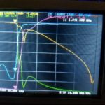
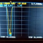
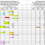
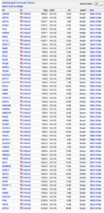 RBN Spots from 40m EFHW at 1800Z on 2021-03-11 The RBN spots from 1800Z show decent results, not too dissimilar from what I am accustomed to seeing from the permanent wire dipole antennas. The test antenna is deployed in a much-less-than-ideal location. The test EFHW horizontal section is running parallel to the horizontal tail of my permanent 160m inverted L, and it is only about 20 feet away. So I’m not too concerned with the locations of spotting stations. I expect to try a POTA activation soon, which will maybe be more interesting.
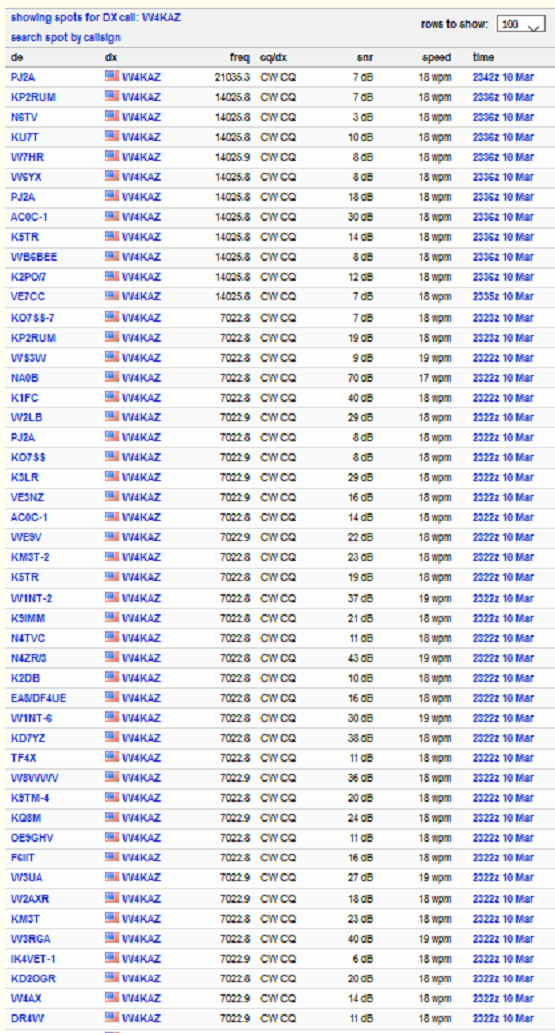
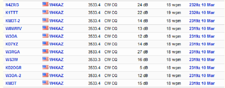
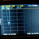
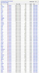 RBN Spots from 40m EFHW at 2345Z on 2021-03-11 Likewise the above set of RBN tests run later, near to and just after local sunset @2330Z, show fairly typical results.Â
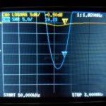
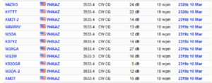 RBN Spots from 40m EFHW at 2345Z on 2021-03-11  * I expected 80m results to be poor but they were maybe better than my low expectations. Nothing great, but certainly good enough for an easy to deploy portable antenna. Better to have some 80m capability than zero capability.Â
Next Question:Â What happens if I use a different transformer?
see part4Â Â EFHW Experiment – Part 4
*
By w4kaz, created on 2021.03.11 at 06:26:00 | last changed on 2021.05.06 at 22:33:03 |
End Fed Half Wave Experiment – Part 1
Construction
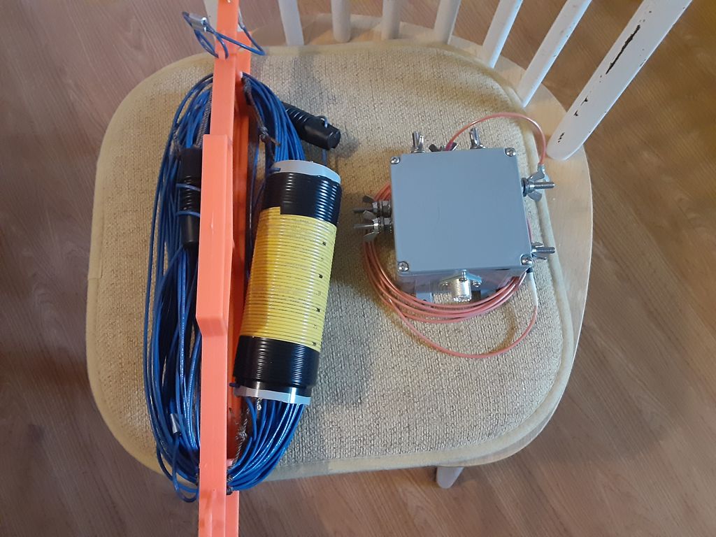 The Initial cut of the antenna and the completed feedpoint enclosure. Having looked at many of the articles available on the WWW, I wound up favoring the design well documented by G0KYA, Steve Nichols. When modeling the antenna I started out using a coil value of 67.5uh. Then I ran the model using the appropriate value of impedance at each given frequency. The coil as shown above is about 63 turns of 16ga solid insulated wire on a plastic coil form of just over 2 inch diameter. That was right at the limit of the amount of wire I could lay down on the available form. The completed coil resonated with a handy 22pf capacitor at 3.855Mhz, which calculates out to an actual inductance of close to 77.5uh. With the coil value known, I re-ran the model to tweak the initial guestimates with actual values of XL for the model’s load. Then cut wire for the 40m leg as well as the 80m tag end. BEFORE tuning wire lengths are long, 71 feet and 15 feet(about 21.6 meters and 4.5 meters).
Inductor
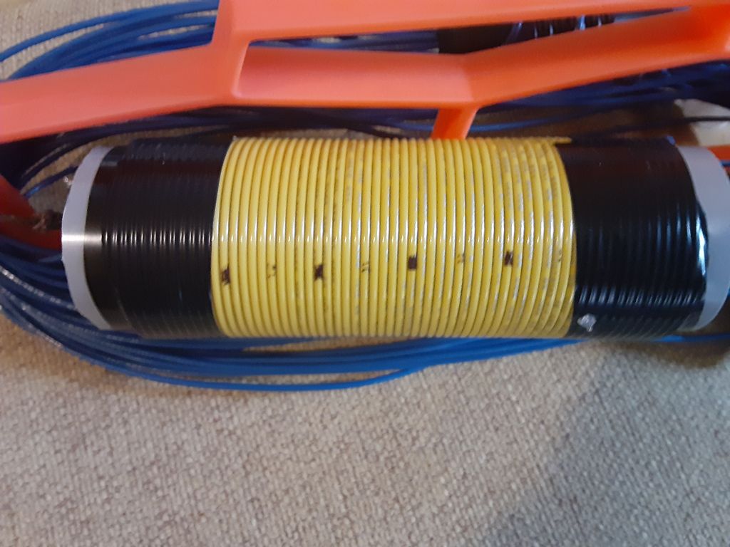 77.5uh inductor, ~63 turns of 16ga insulated wire wound on a 2 inch plastic form. The coil form used seems better for RF than PVC pipe, and is a one-off that happened to be in the parts bin, original source un-remembered. I gave it a run in the microwave, and it showed little heating. It’s other quality is it is 1/16 wall thickness, so most of the weight is the winding. The coil is just over 6 inches in length. The second choice for a coil form was going to be fabricated with a few layers of fiberglass and epoxy laid up on some sort of removable former. The measured value is only about 2/3 of the specified 110uh from the G0KYA document(original designer-????), but it comes down to the trade-off question again. This 77.5uh coil should provide 3400 ohms XL at 7Mhz. Hopefully that will be sufficient to isolate the tail. Actual testing should be interesting.
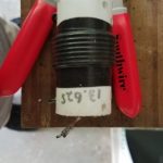
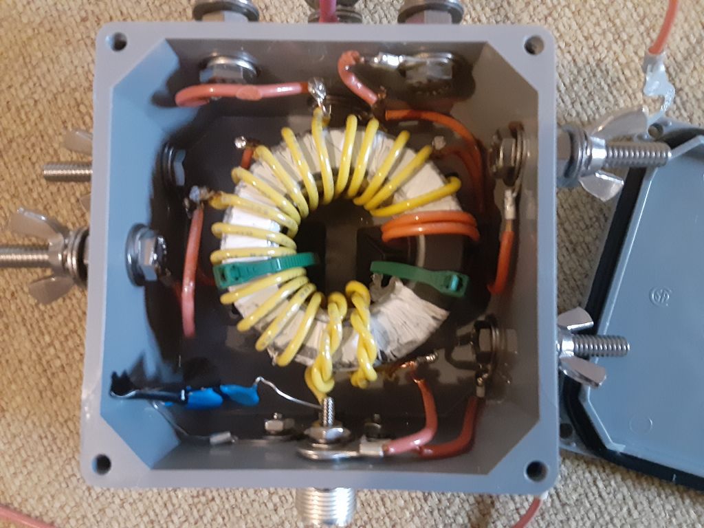 This is the completed transformer installed in terminal box. It has two ft-240-43 toroids together with a two layer cover of teflon tape to make it more slippery for winding. It is wound with a 2 turn primary and 20 turn secondary. Taps are placed on turns #9, #11, #13, #15, #17 and #20. For the capacitor I used three TDK 330pf 3kV 5% ceramic caps in series. I went that route simply because I had more of that value cap handy than either 220pf or an actual 100pf. There are no crossover turns – that seemed counter productive for multi taps. I would have wound the secondary turns more tightly but needed to loosen the turns up some just to fit it in the box and attach the taps.
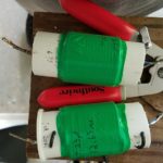
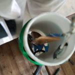
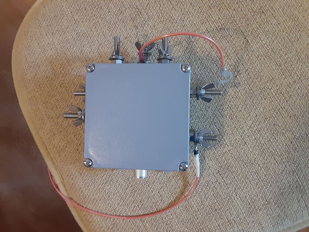 Closed box showing tap wire on top and counterpoise on lower right. The feed point box is an ordinary Carlon 4x4x2 terminal box. Feed thru studs are all 1/4 stainless hex bolts. I expect to attach the antenna to the 10:1 tap(located top center) and use a jumper to short down to the lower impedance taps as needed for best match rather than have the high impedance taps float. The stud on the bottom right is the ground/counterpoise attach point. If nothing else, the multiple taps provide handy places for extra hardware to replace wing nuts fumbled into the sand.
References:
By w4kaz, created on 2021.03.08 at 15:53:33 | last changed on 2021.03.12 at 22:12:18 |
Just about the only wire antenna in common use I had not experimented with is the End Fed Half Wave(EFHW). So WTF. May as well give it a go.Â
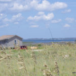
2021 planning had me booking a stay on Cape Lookout National Seashore(CALO) for the end of June rather than the end of July. I tried unsuccessfully to make the reservation in 2020, but could not. Success for 2021. So my FD 2021 will be from Cape Lookout.Â
Given the layout of the cabin I prefer at CALO campground I decided to tinker with the EFHW as a possible solution for allowing multi bands with least effort. The “least effort” factor is growing more important with each passing year. But the EFHW itself piqued my curiosity as well, and it seems it my provide a solution to the “least effort” vs. “works well” conundrum.  Â
So, here lies the experimental portion.  NUMEROUS versions of the classic 49:1 transformer are documented on WWW and in the now ubiquitous scrootoobe video. Version guidelines exist for either 80m or 40m multi band versions. Quite typically I chucked some of that and decided to re-invent the wheel – because what is the fun of experimenting if you are just going to follow the cookbook? Wellll…..not quite that either.
Where to start
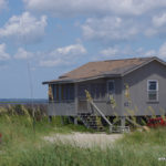
Looking for a 40m size and decided to try modeling out a 40m EFHW fit out with a loading coil and tag end to allow 80m or 75m. The idea is to have an antenna that the floppy fiberglass masts would be able to support easily in the normal 20 knot winds typical on CALO. The feed point will be at about 4 feet high as I expect to deploy it. The mast will support the wire vertically to about 30 or 35 feet, depending on which mast is used(Spiderpole or Jackite or K4TMC). The rest of the wire will be stretched out horizontally with the coil supported by a second mast.
This deployment will have 80m or 40m basically functioning as half wave in an L configuration. 20m will probably have a larger horizontal component than the vertical section, and if it works there 15m/10m will provide who-knows-what. i.e., “PERFECT!” – for values of “perfect” where whatever happens is perfect.
Modeling showed best result with the wire between the feed and the load at a longer length than I expected at 70+ feet.  Using insulated wire for actual construction, I expect that to be shorter in real life.  I plan to test with a .05wave counterpoise, and use a 6 foot coax jumper at feedpoint. The real feedpoint will be a current choke at the end of the coax jumper. It seems likely the shield of the coax jumper will act as another counterpoise. Maybe another choke at the radio end.
Transformer Conundrums
The item I had more questions about was the step-up transformer. A lot of conventional wizzdom surrounding the 7:1 turns ratio versions. I chose to give myself more options and provide multiple taps, and use the larger ft-240-43 size toroid to allow 100w.  Hopefully this will give less core heating. Then two turns vs. three turns on the primary was considered. Initially I favored using three turns on the primary.  I expect 80m to be more useful than 10m going forward.  Physical reality – two turns seemed more practical with the 16ga wire I used.Â
The other wildcard I threw into the construction detail was about sticking to the “norms” of putting the taps on nice-and-easy turns ratios.    While waiting on my toroid order to arrive, I stumbled across N8NK’s videos. I found the playlist on EFHW and UNUN’s interesting viewing. The main idea I fortified was to tap the toroid in several different places. That would have been more versatile using 3:1 windings. Even with 2:1 windings I still liked the range of impedances available by placing “irregular” taps, i.e not on the even multiple windings. With 3:1 I had expected to place the taps on every 4th turn. With 2:1 windings I thought maybe every 3rd turn but with 6 taps every 2nd turn was “good enough”.
The only genuine benefit that conventional “even numbered taps” provides is ease in predicting the transformation factor(i.e., 7:1 turns gives 49:1 step up). To switch the flip I decided to tap the transformer at 4.5:1, 5.5:1, 6.5:1, 7.5:1, 8.5:1 and 10:1. (FWIW, that should be stepping 50 ohms up to about: 1013, 1513, 2113, 2813, 3613 or 5000 ohms.) Just for grins, it is easy to test with the ordinary antenna analyzers and a resistor test box(or well stocked junk box). Â
If it is important to your thought process, measure the damn unun to be sure. To simplify, the secondary is actually tapped on turn #9,#11,#13,#15,#17, and #20. With 2 primary turns and just 5 taps on secondary, tapping every 3 turns at #8, #11, #14, #17 and #20 should allow matching impedances of 750, 1513, 2450, 3616, or 5000 ohms. That includes the obligatory 7:1 ratio for purists. I only chose to use the odd taps as an appeasement to my increasingly contrarian curmudgeonly nature.
Precision Optional
 I figure to just use the antenna with the tap that provides the best SWR. I can then produce a cheat sheet for each band. I would like to have a best choice for each band. If it turns out the same tap works best for all bands – so much the better.  If they are NOT all the same tap I also want compromise choices that will allow one tap to allow operation on several bands without moving the tap. Another tradeoff option – sometimes moving the tap will be easy, sometimes inconvenient.
Functionally we can call it good if some doing RBN compares to permanent dipoles prove it to perform acceptably. The truth is I don’t care what the actual step up ratio might be. I just want the antenna to function, and experimentally finding a good tap is “good enough”. We are hoping that the taps provide enough options for multi-band operation with a good match. It will be nice if a single tap is good on all bands. It is not a deal breaker if changing bands requires moving a tap that can be reached at ground level.
Engineer the possible. Mind the trade-offs, because “best” can be the enemy of “good enough”.
Related Links(updated 2021/03)
End Fed Half Wave Experiment – Part 2
End Fed Half Wave Experiment – Part 3
nonstopsystems.com Multi-Band End Fed Antenna
G0KYA, Steve Nichols.
Â
By w4kaz, created on 2021.01.03 at 12:39:23 | last changed on 2021.01.03 at 12:39:25 | The W4KAZ CW skimmer station reporting to the RBN is down, due to work in the basement in the area of the station. The station is going to be down for at least another two weeks, it needed to be moved to allow for replacing the water heater. Yes, hot water is more important to XYL than CW spots. Go figure.
Station replacement may also be delayed by migrating the skimmer software to a newer computer running Windoze 10. That may turn into a temporary situation, just a test run to verify the backup system is good-to-go.
Been a while since any activity of any sort, website updates included. Been paying attention to other things, have not been active with radio much. Maybe that changes – gonna take it as it comes.
Outage began 2020-12-29. Anticipated end of outage 2021-01-15 at earliest.
By w4kaz, created on 2020.12.07 at 11:47:37 | last changed on 2023.03.27 at 14:57:31 |
Update, 2022/12/08
Ole Elon Musk bought hisself a crime scene when he paid premium money for the Twitter application. Looks like my pessimistic assessment of the evil inherent in social media apps was understated.  A couple of conclusions that fall out of the new info:
1) If Twitter is this bad it is a certain wager that every other social media app is doing the same shit if not worse. Probably worse, especially in case of search engines like google.
2) Records are being destroyed right now at every other social media app.
3) We will find out much of this was directed by the government, factions within government agencies, and/or individual influential political figures.
TWITTER FILES #1….https://threadreaderapp.com/thread/1598822959866683394.html
TWITTER FILES #2….https://threadreaderapp.com/thread/1601007575633305600.html
Original follows:
Fascinating how in only a few years “don’t be evil” mindset morphed into “Embody Evil”, aina?
My original estimation was that social media was a waste of time. Then I thought it might be a viable way to communicate. Now it appears to have evolved into an information cemetery, where good ideas go to be buried, stealthily modified, or more perniciously – forever forgotten. Then you can expect gaslighting as to whether it ever existed.
My own little circle of self flagellation here on the www-interwebzz is where I keep notes on projects. It is easy to search, and provides mechanisms to catalog and gather related items.  When required most of the content edits are dated. All of it for my own uses, but most of it public.
Social media originally set about in a similar fashion, providing less motivated folks a method of establishing a personal web presence for whatever reasons. The major use I found for it was reconnecting with transient friends. Folks who are good people, who one maybe loses touch with when jobs are changed, people move, or whatever.Â
As time marched on, monopoly power was aggregated without limit. Bigg fish ate liddle fish. Monopolists collaborate. Options dwindle. Sinecures established and fortified.
One of the interesting permutations is that a lot of folks who had previously set up blogs or personal websites abandoned them in favor of the “new shiny”.  Another facet is that few people understand that social media sites don’t really work the way they seem to believe they do. Rather than proactively going to content a person wants to see, folks passively wait for the content to be pushed to them via the application.  The applications have minds of their own, and their aims diverge from those of the “sheep” they curate.
Social media monopolies evolved and redesigned the concept of a feed. Big Brother pushes curated content HE wants a person to see rather than what a user thought they were signing up for. And Big Brother also HIDES content he does NOT want seen. All via the “Holy AlGore-ithm”, whose arcane ways are mystic and adjudicated by high priests of increasingly Orwellian nature. Â
These problems seem a lot more pernicious in the long run than the whole raft of probable privacy violations – an entirely huge issue of its own. Generally, if the only source for information on a subject is going to be on a social media site, I have decided it is no longer worthy of interest. Pass. Cashiered. Dead Parrot.Â
Printed copies of everything of sufficient interest are now necessary and worthwhile. Otherwise the airbrushes are sure to come out and Trotsky is deleted wherever he might appear. Keep a hard copy of favorite books and reference sources.  DVD copies of any video of interest. And multiple offline backups of all digital content, especially if it might be even slightly politikkkally inkkkerrekkktified.Â
Another example of webb apps gone astray is U-toob. Once a place for individual and start-up creators, U-toob has decided to partner with dinosaur media to try to save their bacon. Dinosaur media video links are now pushed, while many individual content creators are suppressed or extinguished.  Any company that was once associated with a motto “don’t be evil” is probably overcompensating for their own malign intentions. Seems obvious in hindsight. The only surprise is that the evil has been phased in so gradually.Â
So I have come full circle, more or less.  It was bad enough when old school media was pushing propaganda. With old school print media it was once a lot more difficult to 1984[i.e., selectively edit] articles, texts, and scientific journals. Widespread library archives on microfiche were hard to alter. Today the edits happen in real time, and nothing is intended to be permanent.   Now that modern Big Brother gnu media have fully embraced content modification, censorship, propaganda, and behavior modification techniques, it has become more of a roadblock than an information highway. Â
Takes the sheen right off. May as well stay here. All social media terminated. If they want the personal data going forward they can work for it. Lotsa luck with that.
By w4kaz, created on 2019.11.09 at 15:43:10 | last changed on 2021.05.06 at 22:39:49 |
Many thanks to Guy, K2AV for tips, suggestions, and testing assistance to help resolve the following problems.
An unanticipated problem with fixing broken antenna systems is that it begins to work better. Well – “duh”, right?Â
After making repairs to the antenna switch and the 160m inv-L over the past couple of months, the antenna systems are nearing the end of a minor overhaul. Since about May, the CW Skimmer has been using a K9AY as the main RX antenna. For the period of 2 years prior it has been using the 160m Inv L as the RX antenna, until problems cropped up in May 2019[a broken connection on the feedline at the switch box.]
After correcting the broken connection and re-assembling the skimmer station, K2AV reported having spurs on harmonics when testing on 160m. Upon a closer I found several other stations for which the SDR was also generating harmonic spurs on higher bands for signals of 40-43 DB SNR into the skimmer station SDR.  This was resulting in bad spots to the RBN, and as is sometimes noted “results may be unpredictable”.
All of the spurs appear to be caused by overload mixing from nearby BCB stations on 680, 850, 1360, and 1510. Some of the problem was previously handled with the BCB filter constructed with notches tuned for 680 and 850. Upon re-assemble, the BCB QRM was still sneaking in.
The bulk of the issue has been resolved by bonding the BCB filter enclosure directly to the SDR enclosure. In a belt and suspenders approach, I constructed a second filter that has a higher cut off frequency.  It appears to function as designed, notching 1360, 850, and 680. It adds about 20db attenuation at 1510, and rolls off at about 1650 while applying less than a db attenuation at 1800 to allow 160m into the system. This second filter was placed at the input to the skimmer station preamplifier in the hopes of reducing the interference further.
Currently the result appears promising, as the signal SNR numbers from the skimmer seem to have benefited from the dual filtering scheme. Perhaps the stations at 1360 and 1510 were causing more overload than I originally thought. While neither is as strong as 680 or 850 into this QTH, both are over S-9 on the base radio using the same antenna for RX.
So now the curiosity about BCB filtering has been tweaked, and experiments modeling and building alternate filter choices are continuing.
If you are seeing bad RBN spots originating from the W4KAZ skimmer, please email the info so I can attempt to remediate the problems.
Â
By w4kaz, created on 2019.09.29 at 16:44:08 | last changed on 2019.10.18 at 16:56:45 |
NanoVNA
Recently this NanoVNA product popped up on my radar, and like normal, I was a bit behind the group in discovering it. It is relatively newly available, but seems to be rapidly becoming known because it is both inexpensive and very functional. What a wonderful and useful project. There is a group devoted to the project. There is also a secondary product fork recently begun. The second fork will have a larger screen. Software will not be compatible between the two. (update….maybe more than one fork, rapidly changing).
The NanoVNA itself appears to well suited to the home hobbiest, both in price and utility. As an open source hardware design, being produced by various vendors, it is not coming out yet as a mil-spec “ruggedized” product. It is also not $50,000 USD. Also, caveat emptor. The calibration dummy load supplied with the units I obtained measured an intermittent 50K ohms instead of 50 ohms. A second unit supplied a load that measured 43ohms. [I used a known 50 ohm load for the calibrations.]
Dummy loads aside, it appears I wound up with a cheap copy of the cheap copy of the open source hardware. Yet both units appear to function, at least well enough for the 30Mhz of spectrum of interest here at W4KAZ. All images below were captured on a Samsung Galaxy S7, rather than spend a lot of time dorking around with rapidly developing beta software. Truth is – I was in too much a hurry to tinker to take the time for the software, which seems to be FB. Good enough is often “best”. Engineer the Possible. Plenty of time for software later.
Filters Tested
RTL-SDR: The RTL-SDR 2.6Mhz high pass broadcast band filter.  This filter is quite good. Its only drawback is that the cut off is above the 160m band. This helped a lot in testing to find RFI problems, but I needed a filter that allowed 160m. If 160m is not required this is an inexpensive rx only solution.  AE5X also has posted a quickie scan of this filter recently. My own scans…
-
-
RTL-SDR BCB filter, at 3.93Mhz. SWR=2:1, RL=8.63db, IL= 1.4db
-
-
RTL-SDR BCB filter, at 3.93Mhz. SWR=2:1, RL=8.63db, IL= 1.4db
-
-
RTL-SDR BCB filter, at 1.81Mhz. SWR=16.3:1, RL=1.06db, IL= 50.5db
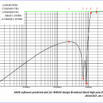
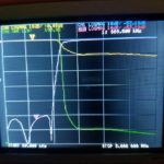
W4KAZ Broadcast Band Filter: While tracking down what I thought were RFI issues on the Red Pitaya CW skimmer, I obtained the RTL BCB filter above. Because its cutoff is at 2.6Mhz I needed something with a lower cutoff frequency.  As a home brew experimental project I came up with a BCB filter, designed using the AADE filter design program, available from KE5FX.   Â
The BCB filter design is shown below, along with the projected rejection. This design is intended to have the cutoff as near to 1 to 1.2Mhz as possible. 680Khz and 850Khz stations are respectively 1.5 and 4 miles from this QTH, and the nearest 680Khz is a 50Kw station. The intent of the design was to null 680 and 850 as much as possible.  This filter also shows a DC short via the 100uh inductor. It can be removed if 60hz mains noise is not an issue.
After construction the filter was originally function tested by checking S-meter levels from the AM band up through HF and a few spectrum glimpses using the Red Pitaya with SDR programs. Using the NanoVNA is a lot quicker. In lieu of computer software for trace captures I just used a field expedient solution – snapping a photo of the teeny NanoVNA screen with my phone.Â
It is nice to see the real world corresponds to theory. The filter shows a 3db shoulder close to design at 1300Mhz. There is a 2:1 SWR shelf across the 160m band. Beyond 2Mhz it rapidly improves. Quite good for my purposes. Also surprisingly good for hand wound coils and ordinary NP0 ceramic caps thrown together without much[i.e., none!] testing of component values. I am not certain if I want to chance tinkering with the tuning of the 680 and 850 notches. Both notches came out about 100 KC lower than designed(not yet shown).
-
-
W4KAZ version of BCB filter. Built using NP0/C0G leaded capacitors, t-80-2 torroids, and a 220uh choke.
-
-
AADE predicted performance plot of the w4kaz BCB filter from DC to 10Mc. Note the nulls on 680 and 850.
-
-
BCB SWR, insertion, and return loss from 50Khz to 3Mhz
-
-
W4KAZ homebrew BCB Filter 50kc to 30M SWR scan
Band Pass Filters:Â
The following set of band pass filters are all constructed based on the K4VX article “Band Pass Filters For HF Transceivers” . A good project, but these were originally only swept for SWR and not a lot of effort to properly tune them previously. NanoVNA to the rescue.Â
10m Bandpass Filter Â
As originally built, 3:1 SWR range is from about 24Mhz to32Mhz. Minimum is at 25.7Mhz, and its usable on the lower end of 10m.
-
-
10m Bandpass filter scan from 15 to 40Mhz.
-
-
10m Bandpass filter scan from 20Mhz to 35Mhz.
-
-
10m Bandpass filter scan from 20Mhz to 35Mhz.
after NanoVNA tuning, a slight improvement across 10m:
-
-
Tuned 10m band pass filter scanned from 15mhz to 40mhz
-
-
Tuned 10m band pass filter scanned from 20mhz to 35mhz, Minimum at 25.400 Mhz
-
-
Tuned 10m band pass filter scanned from 20mhz to 35mhz, on 10m band
15m Bandpass Filter
-
-
Bandpass filter scan for 15M filter
20m Bandpass Filter
-
-
Bandpass filter scan for 20M filter originaly tuned with MFJ analyzer by SWR
-
-
Bandpass filter scan for 20M filter after tuning with NanoVNA
40m Bandpass Filter
Able to tweak the 40m filter from -29.4db to -35.7 db, and filter covers 40m band easily.
-
-
Bandpass filter scan for 40M filter before re-tuning using NanoVNA
-
-
Bandpass filter scan for 40M filter after re-tuning using NanoVNA for a 6-7db return loss improvement
-
80m Bandpass Filter
????where’d it go?!?!?!?! This one was misplaced somehow……????
160m Bandpass Filter
Very bad news on 160m filter. Looks like a new repair project – not even close to “good enough”!
-
-
Bandpass filter scan for 160M filter – BAD news
-
-
Bandpass filter scan for 160M filter – BAD news
By w4kaz, created on 2019.09.28 at 12:41:11 | last changed on 2019.09.28 at 12:41:13 |
2019 brought another solo operation for IOTA, but return to Cape Lookout for the event. Weather was much better than 2018, the only WX challenge being the winds. Normal for the islands on the NC coast, and very agreeable for comfort, but it caused the only bit of trouble for the antennas.
Antennas were set up on Friday. This year two folded dipoles were used, one for 40m and the second on 20m. A hy-gain AV-18VS vertical was set up in the unlikely event 15m or 10 would open. (Neither did for me)
Checking the tuning on the antennas had me chasing shadows for too much of Friday afternoon. After sorting out the feedlines, there was still an SWR problem on the 40m folded dipole. These had been tested at home before the contest, but had been tugged on quite a bit trying to straighten the mast in the high winds. So as a fallback measure I hoisted the 40m/20m trap dipole, and tabled the folded dipole problem. In the end it turned out to be a problem with the antenna analyzer rather than the antennas. Since it was already in the air, I just re-positioned the trap dipole to be at right angles to the folded dipoles. But that was after all too much walking from shack to antenna several times looking for problems.
-
-
W4KAZ IOTA 2019
-
-
W4KAZ IOTA 2019 Antennas
-
-
W4KAZ IOTA 2019 Antennas
-
-
W4KAZ IOTA 2019 Antennas
-
-
W4KAZ IOTA 2019 Antennas
-
-
W4KAZ IOTA 2019
-
-
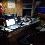
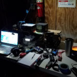
W4KAZ IOTA 2019 station
-
-
W4KAZ IOTA 2019 station
-
-
W4KAZ IOTA 2019
The remainder of Friday evening was spent relaxing. It was more of a vacation than an operation, so time for beverages and a nice cigar was available. A nice spot for stargazing was found on the front steps to the cabin, and several nice meteor streaks crossed the Milky Way.
One of the best moments was a visit by Chris, WX4FLY. Really enjoyed meeting Chris, learned a lot of info in our chat. I also got an eyeball QSL card that may be one of the best custom cards I have run across. Thanks Chris.
-
-
WX4FLY eyeball QSL
Radio conditions at the start of the contest were poor. Radio conditions in the afternoon were poor. Radio conditions in the early evening were poor. Radio conditions overnite were poor. Interest in operating the contest was low, so it was all done in a series of segments lasting 30 to 60 minutes. After a decent hour or so on 40m after it opened, I received a final distraction in the form of a phone call from a long lost acquaintance. Also a cold beverage and a nice cigar.
| Call |
SO2R |
Remote |
CW Qs |
CW Mults |
Ph Qs |
Ph Mults |
Op Time |
Score |
Club |
| W4KAZ |
* |
* |
84 |
20 |
16 |
5 |
10 |
18,750 |
PVRC |
I included an extra day on the end this year to allow packing up to be more relaxing, allow more relaxing, beach side relaxing, and to allow a bit of relaxed operating in an activation for Parks On The Air. The parks hunters were a lot more plentiful than IOTA contest QSO’s, so I handed out 60 or 70 Qsos for Cape Lookout Seashore, a successful activation. For that I used the vertical antenna on SSB, just to give it a shakedown of sorts. All of the antennas and outdoors kit was packed before sundown, and another enjoyable evening of looking for a good fireball followed.
The island was hit pretty hard by hurricane Florence in 2018, and again by Dorian in September 2019. It had changed since 2018 IOTA, and I imagine it will have changed again. Hopefully damage was not as severe as the cabin area to the north, which had a new cut that ran directly through the cabin area, plus lots of other cuts and beach erosion.
The stiff breeze helped keep the islands indigenous obnoxious life forms under control until almost time to leave. Win. Win. Win.
More interesting than the IOTA contest……The lack of decent 20m conditions had me out experimenting with the camera instead.Â
And that, a sprinkling of meteors across the Milky Way, combined with the mild weather to make the trip a winner..
Â
By w4kaz, created on 2019.09.16 at 09:04:17 | last changed on 2025.01.06 at 10:05:54 |
see: Experimenting With Trap Dipoles – Part 1
Those coil and cap experiments described in part #1 eventually led me to the ‘best’ compromise solution for my situation. In the end I chose to build traps that were resonant below the higher band. I also chose to use cap values on the smaller end of the capacitance value range.
-
-
Sample of original 20m trap using 7 turn coil. This trap experienced SWR shifts under xmit at 100w in CW contest.
-
-
Revised traps for 20m/40m dipole. The traps use three of the TDK capacitors in series for a total value of 23pf. The 14 turn coil used resonate the traps at 12.65Mhz. Inductance calculated as approx 7uh.
-
-
Revised trap for 20m/40m dipole. The trap use three of the 2KV TDK capacitors in series for a total value of 23pf. The caps are mounted in series on a small bit of PCB for a cap value of 23pf. Joints were soldered slightly long with a bit of excess solder in the hopes of a bit of extra heat sinking.
Sadly the Panasonic capacitors are no longer available. Possible TDK replacement are being tested. These TDK caps are physically smaller, and only 2Kv rated. I intend to use these in series/parallel groups once I determine the best values to stockpile. (TIP#x: leaning to several caps in series to extend the voltage rating) (TIP#x: Also decided to mount the caps in slivers of PCB, and use generous solder on the pads as well as not clipping the leads short, all in a hope to have that function as heat sinking).
Antenna Experiments: In testing, these capacitors worked well on xmit for the first 20m/40m trap dipole, but I ran into problems with a 10m/15m trap. Using 33pf with an inductor of about .92uH I had failure of the capacitors while testing the antenna.
As an alternative on 10m I used a bit larger inductance and a piece of rg8x coax as the tuning capacitor(low value approx 8-9pf). No final verdict on this solution yet, but the antenna functioned for light usage in 2019 WPX cw contest. Antennas will be used at 100w levels, so these cap variations should also prove suitable for this project. If weight is not an issue, gimmick caps from coax are viable choices, though I’d not use them with the traps resonant close to the operating frequency.
Alternatively the 20m/40m dipole has now been used in two different contests with success. A second 20m/40m dipole was constructed, using smaller coils and increased capacitance. This second experiment was less stable than the first, with the 20m SWR increasing slowly. Presumably the capacitors were heating and having the same problems as the 15m/10m model.
What Did NOT Work: In the end, the experiments using larger values of capacitance proved to be poor choices for practical reasons. In the case of 10m, the caps failed outright. In the 20m case, the caps showed instability in the form of rising SWR, likely because they were heating. A revised 20m dipole with traps using a larger coil and smaller values of capacitance proved to be stable. Tip#1….Marginal caps can maybe stand the abuse in a trap if the coil is larger.
At this time I also chose to move the resonant frequency of traps a bit farther away(lower) from the operating frequency on new construction. This resulted in :
- the dipole legs being shortened,
- the impedance on 20m seemed more stable,
- The bandwidth on the lower band(40m) was decreased
- Precision in component selection becomes less critical
That set of compromises suit me, as the capacitance values are readily available, and the overall antenna length is reduced slightly, without any serious performance compromises as compared to an ordinary single band inverted V. The antennas will be tuned to favor the CW segments, and if needed I will use the radio internal antenna tuner(at the home station) to find a match for SSB if required for 40m. The tuner would likely only be required at the upper band edge if at all.
What worked well enough – Final Versions Constructed: RBN testing of the trap dipole versus a normal 20m dipole showed enough uniformity in results that I am not concerned with trap losses. The end result was a set of dipoles both for permanent use at home and several variations made as light weight as possible for portable operating. The final 20m/40m dipole for the home station was constructed with the traps resonant at 12.650Mhz. A coil with 14 turns close wound on the 1.5″ form was used with a capacitor constructed of several ceramics in series giving a value of 23pf.
A 40m/80m antenna was also constructed. These traps used a coil of 12 turns on the 1.5″ form and capacitors in series parallel for a value of 100pf. Resonant frequency was 6.65Mhz. For future construction this design will likely be modified to move the trap resonant frequency down to the 6Mhz range by increasing the number of turns on the coils while using the same 100pf capacitance value.
A practical benefit of having the resonant frequency away from the operating frequency is that component selection becomes less critical. By selecting a resonant point below the band rather than on or near the band, it is not required to have values to resonate at an exact frequency. Instead, it is only required that each trap resonates at close to the same frequency. This is easier to tweak by adjusting the coil, and it becomes fairly simple to have traps that can be adjusted to within 100hz of one another. The caveat here is that the dipole legs are different based on the trap frequency – but these need to be trimmed to length anyway. [It is possible to easily replicate antennas if the traps are easy to replicate. ] So for a 20m/40m dipole, it makes little difference whether the trap is resonant at 12.5Mhz, 12Mhz, or 13Mhz, so long as the antenna legs are trimmed properly for each.
My experiments show that having the capacitive reactance at the higher operating frequency be in the order of 400-750 ohms seems to reduce the current flow through the caps. Probably this is enough to allow otherwise marginal caps to survive without heating and/or exhibiting SWR variations on xmit. The voltage rating needs to be sufficient, and this can be aided by using several caps in series. The caps in use here are all 2kv or 3kv, and used in series to increase voltage ratings. This is sufficient for 100w levels, but unlikely to survive at 1kw or 1.5kw. I have also mounted them on bits of circuit board to keep the leads short and provide a tiny bit of additional heat sinking. Again, good enough for 100w, but QRO – probably not.
By w4kaz, created on 2019.09.15 at 15:29:37 | last changed on 2025.01.06 at 10:06:15 |
The Project and Situation: After quite a bit of trying over the past 15 years to find the best way to pull dipoles up into the closely packed trees in the yard it is clear the options are limited. Having the dipoles favor the NE/SW directions are the goal, but the arrangement of the best supports make this difficult. To beat this problem a combination of single band and multi band fan dipoles were used. [No, the “chainsaw solution” is not an option – yet.]
The primary supports are now occupied with supporting a 160m inverted L and another with a vee dipole for 80m. These are not high enough for direction to make much difference, but are in convenient locations. So everything else needs to fit around those two primary constraints.
The current problem is that there is really only one support that easily allows stretching out the legs of a 40m dipole in the desired directions while also achieving a good height for 40m(almost 50′). The other high supports will only allow the antenna to be deployed favoring a N/S direction(i.e., legs are stretched out E/W).
Using fan dipoles has come with its own practical problems. The dense tree branch coverage tends to tangle in the multiple wires of the legs. Then the fan legs have become entangled in heavy winds. So it is both a problem deploying the antennas, but also the SWR issues when legs are entangled after bad WX. An ongoing maintenance issue.
Alternate solution: trap dipoles. With dual band trap dipoles, it seems like it may be easier to arrange the antennas in favorable directions AND at good heights. The traps are relatively small compared to the mess of multiple wires on a fan, so also maybe it will be a bit easier to navigate dense branch cover of the biological deciduous antenna support structures. The downside is in the extra effort required in constructing the traps, tuning them to desired frequencies, and tuning the antenna legs for each desired band.
What’s the frequency, Kenneth?!? Using EzNEC 6 I ran models with trap data. Based on those results I initially decided to use traps tuned for just above the top frequencies of any given band(e.g., on 20m tuned for 14.400). I’m willing to live with the trap losses for the advantage of maintenance simplicity. Models showed tuning traps for the top end resulted in wire lengths that are the same as a single band dipole, or slightly longer. I then chose to build antennas with traps above the high end of the band based on the following.
- A trap resonant frequency above the band results in the dipole wires being the same length or slightly longer than the single band dipole at the trap frequency
- A trap resonant frequency below the band requires the dipole wires to be shorter than a dipole for that band. This might be worth pursuing if trying to reduce the antenna length.
- there were already a few spare dipoles laying about, and if the traps project flopped they would still be usable mostly intact if traps designed above band,
- I’ll probably be mostly using them on CW so maybe a tad less loss with trap rez at opposite end
- the gut feeling that a 20m trap resonated at 13.900 would maybe have more loss than the trap at 14.4 when used at 14.025.
- NOTE: SEE Part 2 for notes on how these initial assumptions changed!
Research: The traps will inevitably add unwanted weight to the antennas, and I wished to keep them as lightweight as possible. The reasoning for light weight was to extend the project to portable dipoles deployable on telescoping fiberglass masts. So I ruled out using one of the many coaxial trap designs simply to save weight where possible. For coil forms I chose to use small pieces of 1.5″ plumbing waste pipe cut from small sections of what is sold in the US as a “drain tail piece”. This is thin wall pipe, and much lighter than ordinary schedule 40 PVC. The second form material tried AND ABANDONED is 3.4 inch PVC sched 40.
Excluding the coax trap articles, there are relatively few trap dipole projects written up or documented in places accessible via internet searches. The best[most relevant] source is an ARRL antenna book article on a 2 band trap dipole. W8JI also has some interesting trap info published. Although it does not cover the specifics on the options I chose, it led me to the final result. My choices were made based on materials already on hand(wire, capacitors, and coil form material). Engineer the possible.
Initial Trap Construction: The available values of capacitors also drove the selection of trap resonant frequencies. On this point I made an effort to follow W8JI’s information and make the traps resonant off of the desired operating frequencies to minimize trap losses. Beyond this guideline I could locate nowhere any info to indicate if certain values of inductance vs capacitance were better or worse. A larger inductor will allow the antenna to be shorter overall, but the length of the dipole legs was not a restricting parameter for my project. This was merely about having the dipole resonant on 2 bands. Also, the capacitors are 2KV and 3KV 5% tolerance ceramics from Panasonic that I have used previously in band pass filter projects with great success. (NOTE: MORE ON THIS LATER!!!)
Coil Guidelines????: Guidelines for winding the coils are also a bit of guesswork, beyond W8JI’s testing results that show the highest losses occur on the resonant frequency of the trap. I simply started with the inductors, targeting a value of 6uh, initial turns counts generated by a random calculator found via internet search. Then trial and error on actual coil winding. Calculated inductances are based on trap resonant frequency measurements recorded and on the assumption the 5% caps were the most accurate component. Inductances are then calculated from cap face values and resonant frequency.
Test coils for the traps were close wound with #14 THHN stranded housing wire. They were close wound by hand as tightly as possible onto the forms. Coil Q is probably lower than it could be, but the close winding was a compromise accepted for ease of construction and ease of replication. Four inch lengths of 1.5″ waste pipe and three inch lengths of 3/4 inch PVC were tried. The latter were discarded as unsuitable.
Experimenting With the Coils and Caps: The 5% Panasonic caps on hand typically measure very close to the marked nominal values, much better than any 5% or 10% silver mica caps I have used in similar projects. I found that coils wound with similar technique and the same number of turns would reliably resonate within a range of +/-100 to 200hz. Generally the accuracy and reproducibility is better at 7 and 14 Mhz than at 28Mhz. The coils at the higher frequencies have fewer turns, and smaller differences in inductance and capacitance have a larger effect on resonance.
-
-
Initial coil test data
A group of several capacitor values were used along with an MFJ-259C as a grid dip meter to find the resonant frequencies. Pickup coupling coil was a coax jumper terminated on the business end with gator clips and a short length of #14 wire formed into an adjustable sized loop.
Some initial experimenting with the number of turns on the inductors was based on these available values of fixed capacitors. The first inductor was 12 turns on the 1.5″ forms, then resonance was tested with the values of capacitance that were on hand, or able to be easily derived using series and parallel pairs. It was then relatively simple to find the number of turns needed to be able to produce a trap resonant at a given frequency. I also wound coils on the same form material using 7 and 9 turns, and measured resonance for these.
Experimenting With Trap Dipoles- Part 2
|
|