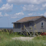
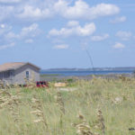
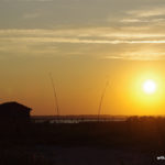
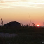
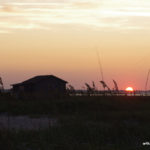
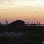
The 2025 IOTA was run from one of the cabins at Cape Lookout(Iota NA067 and Pota US-0683) using the call sign N4C. Ops N4YDU and W4KAZ. N4YDU made the decision to tag along for the 2025 Iota contest outing. As always, having a world class operator means the radio will get a lot more actual use than it would have had I been alone. I am betting the log accuracy will be better too, at least for the YDU QSO’s. 😮
After returning from Field Day a month earlier I gave a bit of consideration to canceling the IOTA trip to Cape Lookout. Then decided to go ahead and keep the trip as scheduled. I’m not even sure if I nudged N4YDU or he asked if I was going, but after the first contact I made sure Nate knew there was plenty of room if he chose to make the trip. And plenty of operating time to fill if he chose to do it. “Highly motivated operator” is not a label I would ever apply to myself. My own interests are more about seeing what works and what does not.
WX es environmental konsiderationz
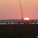
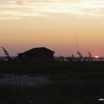
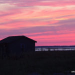
As luck would have it the weekend of the contest brought a few days of clear weather. The “weather tax” this time around was sticky-hot-humidity. Not only was the temperature elevated, but the wind was very mild for the NC outer banks. There were a couple of points where we even had dead air, drawing out the biting kritterz of the insecty sort. Gnats and green-head biting flies. At one humorous point, a literal cloud of gnats. Bitey-bitey!
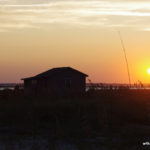
Spraying the cabin window screens helped limit the gnat incursions into the cabin. Ants were present but thankfully not into the food and refreshments. Battery fans provided some moving air overnight to help permit sleeping in the ick. Even the rudimentary cabin was much more comfortable than setting up in and living in a tent in the style of a tropical DXpedition. Window screens, running water and a flush toilet beat the shit out of roughing it like the days before industrialization.
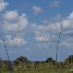
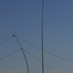
Antennaz? We are doing WHAT for Antennaz?!?
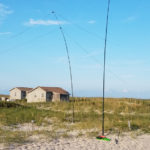
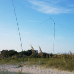
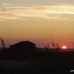
Maybe that’s how the conversation got started with ‘YDU, because I know I texted him to see if he had ever dorked around with a 40m OCF dipole. I had already decided to experiment using a 40m OCF fed directly with 300 ohm window line run back to the shack into a 4:1 balun, and a short coax jumper from balun to a tuner. The second antenna was to be a 59 foot doublet(K2AV suggestion from 2010) from FD and (failed)WPX. Once YDU jumped aboard ship he verified function of his butternut vertical and that was added to the list. For backups I had along a selection of other things(trap dipole, EFHE, linked dipole, etc) that we could have used in a pinch.
The OCF and the doublet were set up favoring Europe, parallel to one another and about 80 or 90 feet apart. The modeling on that seemed ok, but in hindsight I doubt I would do it that way again. The vertical was deployed in a mostly clear area to the NE of the doublet. The wire antennas were supported by 30 foot telescoping masts that are self supporting when mounted in the screw-in ground anchor bases. All of the exterior work got done Thursday afternoon after catching an empty slot on an earlier boat than the 2pm ride booked.
Since the OCF was fed directly with the 300 ohm window line and the balun located just a coax jumper away from the radio, I presume without actual measurements that the feedline was radiating in random directions along with the antenna itself. Probably not ideal, but the QSO’s got logged anyway. In practice there was little difference between the doublet and the OCF, while the vertical showed occasional improvements on some signals. FWIW the doublet had marginal less static/white noise/QRN than the OCF.
Radio? Where the hell is the stupid adapter? Why is this an RCA jack?? WTF????
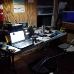
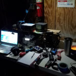
Setting up the station was an exercise in “where is that cable”, since the last couple of times had been with the K2 instead of the K3. Everything needed was there…somewhere. The Elecraft K3 was used. Logging under Writelog, which took YDU a while to adjust to his preferences. The wire antennas were both routed from their baluns to an MFJ tuner that was used as an A/B switch in the tuner bypass positions. The tuner’s antennas routed to the K3 antenna one position and the vertical was routed to the K3 antenna 2 position. The K3 internal atu was used for matching to the wire antennas, and not generally needed for the vertical. After pulling a bad set of headphones everything was working. Too easy. It is NEVER that easy.
Contest? There’s a Contest today?
N4YDU started out hot from the gates and chased mults and called CQ. 15m was the big surprise for me, as the 15m band has seldom been open during this contest for this QTH over the past several years. The low USA activity levels make the first 8 hours of the contest somewhat of a challenge. The EU stations tend to concentrate on working other EU. Since the Cape Lookout QTH is also a POTA entity, for my part I alternated calling CQ for IOTA and POTA. The self spotting rule change allowed us to post spots in the POTA system. This resulted in some decent rate hours that have been really dead in the past. I hit 15m and 20m hardest for POTA, and neglected 40m entirely. Probably left a lot of POTA Q’s on the table by never getting to 40m.
As the afternoon grew longer it sounded like 20m was ready to open pretty well to Europe, so I wanted YDU to have a shot at the possible higher rates. Also better to have the better op on the radio when 40m opens. While it was nothing like a major contest rate wise, the best rates we had were centered on local sunset on 40m. YDU pulled the plug for the evening around 0400Z. The early morning/local sunrise hours did not produce any JA, KH6, ZL or VK, much to our disappointment. 80m over-performed beating out 10m by 16 QSO’s and 4 mults.
The Good, The Bad, and The Ugly
The Good: As always, enjoyed have N4YDU along for the trip. We had a bit more time for setting up as we were able to catch and earlier boat to the island than the one scheduled. That alone gave us an extra two hours to set up antennas and such. All of the antenna systems functioned as expected and no repairs/redo’s/debugging was required on the antenna systems. The radio systems were “mostly” ready to plug and play, but I will need to repack/review/reequip the radio set ups with the goal of having each radio packed individually as a stand alone unit. WX goodness was complete lack of thunderstorms, a rarity over the past 10 years.
The Bad. The worst part was weather related. Although we were spared any electrical storms, that was all due to a high pressure system sitting over the region that also drove the temps into the mid 90’s (95F/35C) with the associated oceanside high humidity. Just like being in Louisiana again! Except I’m no longer acclimated to the norms of S. Louisiana weather. Nathan took to dunking his shirt in ice water to get some relief. Normally Cape Lookout has a consistent breeze blowing that helps mitigate the heat, but we caught a couple of spells of nearly still air.
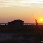
The UGLY: Bugfest 2025. The other downside to the still air is that it gives the biting flies and gnats(“Gnatzi’s”) freedom to roam. Just like being in Louisiana! Humorous anecdote reserved for in person grinz.
Addendum(2025-08-09): What Next?
The question naturally arises: “Is this 2025 Iota antenna plan how I would do it again?”. The answer that intermediately comes to mind is “NO”. But that would be the case just out of the curiosity of trying something new. If I were to deploy the same antennas again, I would have put the two wires at right angles based on how similar they functioned this year. Also, after some more research and modeling, I think the OCF needs to be rebuilt. It seems like feeding at 40% point makes more sense, giving a better match on 15m and 10m while keeping 20m and 40m at a low swr. (TO BE TESTED, 40m OCF with 27.5′ and 41.25′ legs[8.38m and 12.57m]). LINK: “Off Center Fed Antennas” W3TB youtube presentation, April 2023 WCARES. Also thinking about how and 80m OCF would fit into the favorite Iota QTH. Then there are the permutations and combinations yet tried(OCF and EFHW, doublet and EFHW). The grass is always greener, aina?
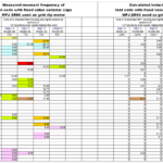
3830 scores for Multi stations and band breakdowns
POTA Results
POTA hunters came in for the Q’s, and there were 42 P2P Q’s confirmed so far in the POTA system. Just guessing, but it looks like about 150 to 200 Pota hunters checked in, and that is probably a conservative estimate. Thanks fer the Q’s hunters!
Pota from Calo this year:
Screenshot 2025-08-07 – POTA activations from US-0683, Cape Lookout National Seashore
By w4kaz, created on 2025.03.15 at 19:27:17 | last changed on 2026.05.04 at 20:52:25 |
Looking at a few of the promo vids folks have posted so far about the Pota33H mast I decided to take a chance on it and the order arrived late last week. On first look I thought it might not be long enough to stretch to the 30-ish feet, but I underestimated the strength of the carbon fiber. For its short length it has a lot of sections inside, and the top section is about 1/2 inch diameter tube. Thicker tubes are stronger than thinner. The carbon fiber provides a lot of strength in a much thinner level of material, so it should be just fine. I expect it will have less flop/droop than any of the fiberglass masts. But the folks who got it made should be happy, it seems to check all of the design goals any backpacker might have for compact, lightweight, and strength.
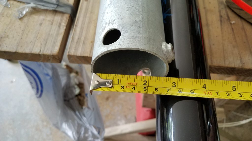
It did have a couple of caveats for my own uses. If the mast were a full 48 inches I would like it better, but it was designed for its short collapsed length. The second caveat is more of an impact for my own purposes. The base piece at the bottom of the mast is heavy duty, and quite thick. The end cap is thick and sturdy. So thick that as delivered it is just slightly too large to fit in one of my favored mount methods, a trailer hitch post holder.
The end cap from the pota33H after filing is about 60mm diameter. It fits into one of the hitch mount post supports, but not the other.
The hitch mount that does not accept the Pota 33 mast appears to also be about 62mm diameter. Perhaps it is out of round? Thicker walls? Will need the micrometer to find out, the two different pole receptacles appear to be the same size to eyeball mark 1.
The hitch mount that accepts the Pota 33 mast is about 62mm diameter.
Pota 33 base fits for this hitch mount after a bit of judicious filing
Pota 33 base is too fat for this hitch mount
The truck hitch receiver with a step extension that supports the telescoping fiberglass mast. The mast du’jour is the Jac-kite 31 footer. Plus assorted extra junk in the truck bed.
After trying the mast in both mounts it was clear it was very close to being able to function in one of them. After a few passes with a file around the widest part of the pota33h’s base cap, it was able to just barely slide in to the hitch mount. That will make deploying portable a bit more convenient. Kinda hate putting the file to a massage brand new sort-of-pricey mast, but WTF. Not like I was sending it back anyway.
Also, the pota33h should be FB for use in the screw in earth anchors I use for the beach side deployments. As long as it works with those its worth trying.
The unknowns now are: What it will do with a real antenna attached? Will the friction fit hold in the wind? Will the friction fit hold an antenna without collapsing in the 20 knot winds common on Cape Lookout? Will the carbon fiber be better than fiberglass when stressed? Will the thin wall carbon fiber tubes crack and split, compared to fiberglass more or less likely? Will sand prove to be a bigger problem for this mast than others? Will it really be less floppy than its fiberglass predecessors? Will sand cause it issues? Will it have difficulty being lowered after a roll in the Cape Lookout sand? TBD…soon!
By w4kaz, created on 2025.01.06 at 10:01:53 | last changed on 2025.01.09 at 16:30:42 |
After a detour to building the 2 band trap dipoles using rg-316 type coax, the worm turned. The failure of a couple of the coax trap antennas due to incomplete sealing and weather proofing the coax became a problem. The antenna at home failed. Two of them. Then the antenna being used for portable ops failed during the 2024 NC QSO party. In the meantime, the home antennas built from coils and capacitors for 40m/20m are still in use 4 years later with no change in resonance points.
Rather than continue with a seemingly fragile system it was time to revert to the coil-and-cap design. Avoiding the cap failures previously experienced on the 10m/15m antenna is addressed by using caps with low enough values to be appropriate for the 10/15 version. So a supply of the TDK ceramic caps was laid in. These caps have 3KV and 6KV ratings. Parts#810-CC45SL3JD080DYGN (example is 8pf SL 6kv) from mouser. TDK Data Sheet for Sl ceramic capacitors.
For the 10m trap a value of 10pf was used, with 16 turns of 18ga stranded wire tightly wound on a 1 inch diameter piece of fiberglass tube. (calculated inductance is about 3.25uh) This originally resonated about 27500, but crept up after taping and sealing to 28000. Decided to roll with them as constructed. These may be fragile, too fragile for portable use, as 18ga wire was also used for the connections. NOTE: USE LARGER GA WIRE FOR CONNECTIONS.
The “tricksey” part discovered previously is that using caps with a large enough reactance on the upper band helps them survive by limiting the current actually flowing through the capacitor. At the 100w levels the voltages are less of an issue than the current handling. Using parallel-series combinations can also help, depending on what value caps are available.
The downside is that the inductance value to resonate the trap for 10m becomes relatively large. This makes tuning the antenna for the 15m band “tricksey”. The 15m tail is short, maybe 15 inches from the relatively large inductance used in the trap. When trimming, very small trimmings move the 15m resonance quite a bit more than on a normal 15m dipole. The good news is that the 10m band is only very slightly effected by trimming wire on the 15m side of the trap. The 15m tails needed to be replaced and re-trimmed after trimming a 2 inch bit of wire moved resonance from 20.85mhz to 21.65mhz. oops. SMALL SNIPS FOR 15m tuning!!!!
After trimming, the 10m/15m antenna is good from 28000 to 28750, and also covers the entire 15m band. STOP….DO NOT TRIM AGAIN!
The 20m/40m version is built with a trap resonance at 13.65mhz. The 20m legs are approximately 15ft long. The 40m legs will be about the same. (?actual measurements?) Total antenna length of about 60 feet.
Both of the 2019 home 20m/40m trap dipoles can be easily matched with the Kenwood TS-590 internal tuner for use on 10m as well, which provides options. Worked JA’s on 10m using the 20m/40m trap dipole several times now. The new version for the 20m/40m portable does NOT tune on 10m, probably because of the different value of capacitance/inductance used, or maybe because the new antenna traps resonate at 13.65Mhz instead of 12.5Mhz. The new trapped antenna covers the entire 20m band, with the highest SWR of 1.5:1 at 14000-14015. The 40m band is below 1.5:1 SWR from 7000 to about 7250, with the swr going to about 2.3:1 at 7300.
(For future testing, add turns
Using the new 1 inch o.d.(~25mm) fiberglass form material as the coil form and the TDK capacitors:
Freq———Capacitor——-–# turns calculated——#turns actual——-
27.7Mhz—>10pf————->12 turns (approx)—–> 12 turns, 28Mhz(use 12.5?) (calculated inductance of 3.25uH as constructed)
20.66Mhz–> ?????
13.75Mhz—> 34pf————>16 turns —— ——–> 16.5 turns, 13.65Mhz (calculated inductance 4.04uh)
6.75Mhz—-> 16.33 turns
[edited for links and notes, 2023/07/15] The original trap dipoles were constructed using coils and caps. Using Rg-58 for the coax style trap dipoles was rejected because of the weight and size of rg-58 coax traps. Using RG-58 defeated the primary goal of making the antenna as light weight as possible.
Somewhere I picked up the notion of using rg-174 or rg-316 type mini coax to make the traps. It looks like the voltage ratings on the rg-174 is higher(1100v rms), so that was chosen for the first experiments. If luck holds out, the tiny coax will be sufficient for use on the dipole traps for a full 100w CW. Using the smaller lighter mini coax will allow for lightweight construction from easily available materials that can be easily supported using telescoping fiberglass masts like those available from Spiderbeam, MFJ, or Jackite. i.e., perfect for portable, field day, rover QSO parties, or POTA/SOTA.
The trap calculator program hosted by KC1KCCgave me some starting numbers to work with, and actual trap measurements came out quite close to the calculated values. [alternate calculator at K7MEM]  The traps are built with the coax coils wound reasonably tight to the form, and the coils were taped down with electrical tape prior to taking measurements. These are all wound on small sections of the same sort of plumbing drain tailpieces that are 1.5″ od (38mm od). (e.g., in the US available from Lowes or any hardware store selling plumbing supplies.) The table below are of traps as built and tested with the nanovna.
frequency
turns rg-174
27.7
3.33
20.66
4.33
13.75
6.1
6.75
10.3 [calculated]
Update, 2024-04-04
Received a new 1 inch o.d.(~25mm) form material that is lighter. testing.
Freq———–# turns calculated——#turns actual——- 27.7Mhz—>5 turns (approx)—–> 5 turns, 24.8Mhz(use 4.5?)
20.66Mhz–> 6.25 turns————> 6.25 turns, 19.65Mhz(use 6)
13.75Mhz—> 8.75 turns ——–> 9 turns, 13.5Mhz & 13.7Mhz
6.75Mhz—-> 16.33 turns END 2024-04-04 Update
Test Antennas:
The test antennas were built for the CW segments of each band. With the best SWR centered on the xx.070 area it will probably give enough coverage for both CW and SSB operation without a tuner. An 80m/40m version will require tails for 80m adjustments.
Testing of two antennas was done before the May 2022 CQ WPX CW contest. The 20m/15m version tuned easily….after I figured out I was working on that instead of the 10m antenna. Read those labels, because at least I had them labeled properly when they were built several weeks earlier. The 10m/15m version also tuned easily.
[aside: the 15m/20m trap is now in service as the skimmer station antenna, after a recent storm broke the 160m inv-l]
Although I missed the WPX contest, I soon got a chance to do antenna testing at 100w levels.  Both antennas handled the power easily with no signs of SWR rise. Both were tested at 10 seconds, 30 seconds, 60 seconds and five minutes of CW key-down.
Hoping for good conditions in FD to allow testing of the 10m/15m version. Sunspots, do your thing!
[2023-07-15 additional notes] The coax traps began showing swr problems on 10m after a few months in the weather. Expecting this to be a problem with water intrusion. testing the use of WeldBond glue as a sealant. [alternative….Elmers ProBond] Also testing the adhesive as a sort of q-dope to seal the coils on the form.
By w4kaz, created on 2019.11.09 at 15:43:10 | last changed on 2021.05.06 at 22:39:49 |
Many thanks to Guy, K2AV for tips, suggestions, and testing assistance to help resolve the following problems.
An unanticipated problem with fixing broken antenna systems is that it begins to work better. Well – “duh”, right?Â
After making repairs to the antenna switch and the 160m inv-L over the past couple of months, the antenna systems are nearing the end of a minor overhaul. Since about May, the CW Skimmer has been using a K9AY as the main RX antenna. For the period of 2 years prior it has been using the 160m Inv L as the RX antenna, until problems cropped up in May 2019[a broken connection on the feedline at the switch box.]
After correcting the broken connection and re-assembling the skimmer station, K2AV reported having spurs on harmonics when testing on 160m. Upon a closer I found several other stations for which the SDR was also generating harmonic spurs on higher bands for signals of 40-43 DB SNR into the skimmer station SDR.  This was resulting in bad spots to the RBN, and as is sometimes noted “results may be unpredictable”.
All of the spurs appear to be caused by overload mixing from nearby BCB stations on 680, 850, 1360, and 1510. Some of the problem was previously handled with the BCB filter constructed with notches tuned for 680 and 850. Upon re-assemble, the BCB QRM was still sneaking in.
The bulk of the issue has been resolved by bonding the BCB filter enclosure directly to the SDR enclosure. In a belt and suspenders approach, I constructed a second filter that has a higher cut off frequency.  It appears to function as designed, notching 1360, 850, and 680. It adds about 20db attenuation at 1510, and rolls off at about 1650 while applying less than a db attenuation at 1800 to allow 160m into the system. This second filter was placed at the input to the skimmer station preamplifier in the hopes of reducing the interference further.
Currently the result appears promising, as the signal SNR numbers from the skimmer seem to have benefited from the dual filtering scheme. Perhaps the stations at 1360 and 1510 were causing more overload than I originally thought. While neither is as strong as 680 or 850 into this QTH, both are over S-9 on the base radio using the same antenna for RX.
So now the curiosity about BCB filtering has been tweaked, and experiments modeling and building alternate filter choices are continuing.
If you are seeing bad RBN spots originating from the W4KAZ skimmer, please email the info so I can attempt to remediate the problems.
By w4kaz, created on 2019.09.29 at 16:44:08 | last changed on 2019.10.18 at 16:56:45 |
NanoVNA
Recently this NanoVNA product popped up on my radar, and like normal, I was a bit behind the group in discovering it. It is relatively newly available, but seems to be rapidly becoming known because it is both inexpensive and very functional. What a wonderful and useful project. There is a group devoted to the project. There is also a secondary product fork recently begun. The second fork will have a larger screen. Software will not be compatible between the two. (update….maybe more than one fork, rapidly changing).
The NanoVNA itself appears to well suited to the home hobbiest, both in price and utility. As an open source hardware design, being produced by various vendors, it is not coming out yet as a mil-spec “ruggedized” product. It is also not $50,000 USD. Also, caveat emptor. The calibration dummy load supplied with the units I obtained measured an intermittent 50K ohms instead of 50 ohms. A second unit supplied a load that measured 43ohms. [I used a known 50 ohm load for the calibrations.]
Dummy loads aside, it appears I wound up with a cheap copy of the cheap copy of the open source hardware. Yet both units appear to function, at least well enough for the 30Mhz of spectrum of interest here at W4KAZ. All images below were captured on a Samsung Galaxy S7, rather than spend a lot of time dorking around with rapidly developing beta software. Truth is – I was in too much a hurry to tinker to take the time for the software, which seems to be FB. Good enough is often “best”. Engineer the Possible. Plenty of time for software later.
Filters Tested
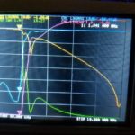
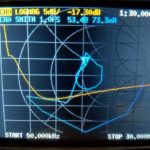
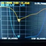
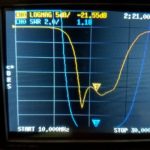
RTL-SDR: The RTL-SDR 2.6Mhz high pass broadcast band filter.  This filter is quite good. Its only drawback is that the cut off is above the 160m band. This helped a lot in testing to find RFI problems, but I needed a filter that allowed 160m. If 160m is not required this is an inexpensive rx only solution.  AE5X also has posted a quickie scan of this filter recently. My own scans…
RTL-SDR BCB filter, at 3.93Mhz. SWR=2:1, RL=8.63db, IL= 1.4db
RTL-SDR BCB filter, at 3.93Mhz. SWR=2:1, RL=8.63db, IL= 1.4db
RTL-SDR BCB filter, at 1.81Mhz. SWR=16.3:1, RL=1.06db, IL= 50.5db
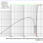
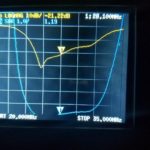
W4KAZ Broadcast Band Filter: While tracking down what I thought were RFI issues on the Red Pitaya CW skimmer, I obtained the RTL BCB filter above. Because its cutoff is at 2.6Mhz I needed something with a lower cutoff frequency.  As a home brew experimental project I came up with a BCB filter, designed using the AADE filter design program, available from KE5FX.   Â
The BCB filter design is shown below, along with the projected rejection. This design is intended to have the cutoff as near to 1 to 1.2Mhz as possible. 680Khz and 850Khz stations are respectively 1.5 and 4 miles from this QTH, and the nearest 680Khz is a 50Kw station. The intent of the design was to null 680 and 850 as much as possible.  This filter also shows a DC short via the 100uh inductor. It can be removed if 60hz mains noise is not an issue.
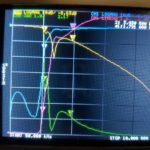
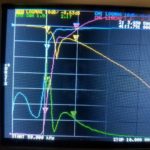
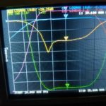
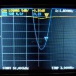
After construction the filter was originally function tested by checking S-meter levels from the AM band up through HF and a few spectrum glimpses using the Red Pitaya with SDR programs. Using the NanoVNA is a lot quicker. In lieu of computer software for trace captures I just used a field expedient solution – snapping a photo of the teeny NanoVNA screen with my phone.Â
It is nice to see the real world corresponds to theory. The filter shows a 3db shoulder close to design at 1300Mhz. There is a 2:1 SWR shelf across the 160m band. Beyond 2Mhz it rapidly improves. Quite good for my purposes. Also surprisingly good for hand wound coils and ordinary NP0 ceramic caps thrown together without much[i.e., none!] testing of component values. I am not certain if I want to chance tinkering with the tuning of the 680 and 850 notches. Both notches came out about 100 KC lower than designed(not yet shown).
W4KAZ version of BCB filter. Built using NP0/C0G leaded capacitors, t-80-2 torroids, and a 220uh choke.
AADE predicted performance plot of the w4kaz BCB filter from DC to 10Mc. Note the nulls on 680 and 850.
BCB SWR, insertion, and return loss from 50Khz to 3Mhz
W4KAZ homebrew BCB Filter 50kc to 30M SWR scan
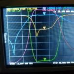
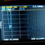
Band Pass Filters:Â
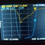
The following set of band pass filters are all constructed based on the K4VX article “Band Pass Filters For HF Transceivers” . A good project, but these were originally only swept for SWR and not a lot of effort to properly tune them previously. NanoVNA to the rescue.Â
10m Bandpass Filter Â
As originally built, 3:1 SWR range is from about 24Mhz to32Mhz. Minimum is at 25.7Mhz, and its usable on the lower end of 10m.
10m Bandpass filter scan from 15 to 40Mhz.
10m Bandpass filter scan from 20Mhz to 35Mhz.
10m Bandpass filter scan from 20Mhz to 35Mhz.
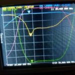
after NanoVNA tuning, a slight improvement across 10m:
Tuned 10m band pass filter scanned from 15mhz to 40mhz
Tuned 10m band pass filter scanned from 20mhz to 35mhz, Minimum at 25.400 Mhz
Tuned 10m band pass filter scanned from 20mhz to 35mhz, on 10m band
15m Bandpass Filter
Bandpass filter scan for 15M filter
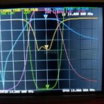
20m Bandpass Filter
Bandpass filter scan for 20M filter originaly tuned with MFJ analyzer by SWR
Bandpass filter scan for 20M filter after tuning with NanoVNA
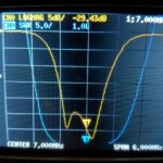
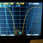
40m Bandpass Filter
Able to tweak the 40m filter from -29.4db to -35.7 db, and filter covers 40m band easily.
Bandpass filter scan for 40M filter before re-tuning using NanoVNA
Bandpass filter scan for 40M filter after re-tuning using NanoVNA for a 6-7db return loss improvement
80m Bandpass Filter
????where’d it go?!?!?!?! This one was misplaced somehow……????
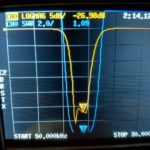
160m Bandpass Filter
Very bad news on 160m filter. Looks like a new repair project – not even close to “good enough”!
By w4kaz, created on 2019.09.28 at 12:41:11 | last changed on 2019.09.28 at 12:41:13 |
2019 brought another solo operation for IOTA, but return to Cape Lookout for the event. Weather was much better than 2018, the only WX challenge being the winds. Normal for the islands on the NC coast, and very agreeable for comfort, but it caused the only bit of trouble for the antennas.
Antennas were set up on Friday. This year two folded dipoles were used, one for 40m and the second on 20m. A hy-gain AV-18VS vertical was set up in the unlikely event 15m or 10 would open. (Neither did for me)
Checking the tuning on the antennas had me chasing shadows for too much of Friday afternoon. After sorting out the feedlines, there was still an SWR problem on the 40m folded dipole. These had been tested at home before the contest, but had been tugged on quite a bit trying to straighten the mast in the high winds. So as a fallback measure I hoisted the 40m/20m trap dipole, and tabled the folded dipole problem. In the end it turned out to be a problem with the antenna analyzer rather than the antennas. Since it was already in the air, I just re-positioned the trap dipole to be at right angles to the folded dipoles. But that was after all too much walking from shack to antenna several times looking for problems.
W4KAZ IOTA 2019
W4KAZ IOTA 2019 Antennas
W4KAZ IOTA 2019 Antennas
W4KAZ IOTA 2019 Antennas
W4KAZ IOTA 2019 Antennas
W4KAZ IOTA 2019
W4KAZ IOTA 2019 station
W4KAZ IOTA 2019 station
W4KAZ IOTA 2019
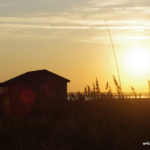
The remainder of Friday evening was spent relaxing. It was more of a vacation than an operation, so time for beverages and a nice cigar was available. A nice spot for stargazing was found on the front steps to the cabin, and several nice meteor streaks crossed the Milky Way.
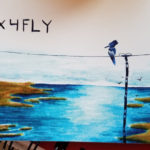
One of the best moments was a visit by Chris, WX4FLY. Really enjoyed meeting Chris, learned a lot of info in our chat. I also got an eyeball QSL card that may be one of the best custom cards I have run across. Thanks Chris.
WX4FLY eyeball QSL
Radio conditions at the start of the contest were poor. Radio conditions in the afternoon were poor. Radio conditions in the early evening were poor. Radio conditions overnite were poor. Interest in operating the contest was low, so it was all done in a series of segments lasting 30 to 60 minutes. After a decent hour or so on 40m after it opened, I received a final distraction in the form of a phone call from a long lost acquaintance. Also a cold beverage and a nice cigar.
I included an extra day on the end this year to allow packing up to be more relaxing, allow more relaxing, beach side relaxing, and to allow a bit of relaxed operating in an activation for Parks On The Air. The parks hunters were a lot more plentiful than IOTA contest QSO’s, so I handed out 60 or 70 Qsos for Cape Lookout Seashore, a successful activation. For that I used the vertical antenna on SSB, just to give it a shakedown of sorts. All of the antennas and outdoors kit was packed before sundown, and another enjoyable evening of looking for a good fireball followed.
The island was hit pretty hard by hurricane Florence in 2018, and again by Dorian in September 2019. It had changed since 2018 IOTA, and I imagine it will have changed again. Hopefully damage was not as severe as the cabin area to the north, which had a new cut that ran directly through the cabin area, plus lots of other cuts and beach erosion.
The stiff breeze helped keep the islands indigenous obnoxious life forms under control until almost time to leave. Win. Win. Win.
More interesting than the IOTA contest……The lack of decent 20m conditions had me out experimenting with the camera instead.Â
And that, a sprinkling of meteors across the Milky Way, combined with the mild weather to make the trip a winner..
By w4kaz, created on 2019.09.15 at 15:29:37 | last changed on 2025.01.06 at 10:06:15 |
The Project and Situation: After quite a bit of trying over the past 15 years to find the best way to pull dipoles up into the closely packed trees in the yard it is clear the options are limited. Having the dipoles favor the NE/SW directions are the goal, but the arrangement of the best supports make this difficult. To beat this problem a combination of single band and multi band fan dipoles were used. [No, the “chainsaw solution” is not an option – yet.]
The primary supports are now occupied with supporting a 160m inverted L and another with a vee dipole for 80m. These are not high enough for direction to make much difference, but are in convenient locations. So everything else needs to fit around those two primary constraints.
The current problem is that there is really only one support that easily allows stretching out the legs of a 40m dipole in the desired directions while also achieving a good height for 40m(almost 50′). The other high supports will only allow the antenna to be deployed favoring a N/S direction(i.e., legs are stretched out E/W).
Using fan dipoles has come with its own practical problems. The dense tree branch coverage tends to tangle in the multiple wires of the legs. Then the fan legs have become entangled in heavy winds. So it is both a problem deploying the antennas, but also the SWR issues when legs are entangled after bad WX. An ongoing maintenance issue.
Alternate solution: trap dipoles. With dual band trap dipoles, it seems like it may be easier to arrange the antennas in favorable directions AND at good heights. The traps are relatively small compared to the mess of multiple wires on a fan, so also maybe it will be a bit easier to navigate dense branch cover of the biological deciduous antenna support structures. The downside is in the extra effort required in constructing the traps, tuning them to desired frequencies, and tuning the antenna legs for each desired band.
What’s the frequency, Kenneth?!? Using EzNEC 6 I ran models with trap data. Based on those results I initially decided to use traps tuned for just above the top frequencies of any given band(e.g., on 20m tuned for 14.400). I’m willing to live with the trap losses for the advantage of maintenance simplicity. Models showed tuning traps for the top end resulted in wire lengths that are the same as a single band dipole, or slightly longer. I then chose to build antennas with traps above the high end of the band based on the following.
A trap resonant frequency above the band results in the dipole wires being the same length or slightly longer than the single band dipole at the trap frequency
A trap resonant frequency below the band requires the dipole wires to be shorter than a dipole for that band. This might be worth pursuing if trying to reduce the antenna length.
there were already a few spare dipoles laying about, and if the traps project flopped they would still be usable mostly intact if traps designed above band,
I’ll probably be mostly using them on CW so maybe a tad less loss with trap rez at opposite end
the gut feeling that a 20m trap resonated at 13.900 would maybe have more loss than the trap at 14.4 when used at 14.025.
NOTE: SEE Part 2 for notes on how these initial assumptions changed!
Research: The traps will inevitably add unwanted weight to the antennas, and I wished to keep them as lightweight as possible. The reasoning for light weight was to extend the project to portable dipoles deployable on telescoping fiberglass masts. So I ruled out using one of the many coaxial trap designs simply to save weight where possible. For coil forms I chose to use small pieces of 1.5″ plumbing waste pipe cut from small sections of what is sold in the US as a “drain tail piece”. This is thin wall pipe, and much lighter than ordinary schedule 40 PVC. The second form material tried AND ABANDONED is 3.4 inch PVC sched 40.
Excluding the coax trap articles, there are relatively few trap dipole projects written up or documented in places accessible via internet searches. The best[most relevant] source is an ARRL antenna book article on a 2 band trap dipole. W8JI also has some interesting trap info published. Although it does not cover the specifics on the options I chose, it led me to the final result. My choices were made based on materials already on hand(wire, capacitors, and coil form material). Engineer the possible.
Initial Trap Construction: The available values of capacitors also drove the selection of trap resonant frequencies. On this point I made an effort to follow W8JI’s information and make the traps resonant off of the desired operating frequencies to minimize trap losses. Beyond this guideline I could locate nowhere any info to indicate if certain values of inductance vs capacitance were better or worse. A larger inductor will allow the antenna to be shorter overall, but the length of the dipole legs was not a restricting parameter for my project. This was merely about having the dipole resonant on 2 bands. Also, the capacitors are 2KV and 3KV 5% tolerance ceramics from Panasonic that I have used previously in band pass filter projects with great success. (NOTE: MORE ON THIS LATER!!!)
Coil Guidelines????: Guidelines for winding the coils are also a bit of guesswork, beyond W8JI’s testing results that show the highest losses occur on the resonant frequency of the trap. I simply started with the inductors, targeting a value of 6uh, initial turns counts generated by a random calculator found via internet search. Then trial and error on actual coil winding. Calculated inductances are based on trap resonant frequency measurements recorded and on the assumption the 5% caps were the most accurate component. Inductances are then calculated from cap face values and resonant frequency.
Test coils for the traps were close wound with #14 THHN stranded housing wire. They were close wound by hand as tightly as possible onto the forms. Coil Q is probably lower than it could be, but the close winding was a compromise accepted for ease of construction and ease of replication. Four inch lengths of 1.5″ waste pipe and three inch lengths of 3/4 inch PVC were tried. The latter were discarded as unsuitable.
Experimenting With the Coils and Caps: The 5% Panasonic caps on hand typically measure very close to the marked nominal values, much better than any 5% or 10% silver mica caps I have used in similar projects. I found that coils wound with similar technique and the same number of turns would reliably resonate within a range of +/-100 to 200hz. Generally the accuracy and reproducibility is better at 7 and 14 Mhz than at 28Mhz. The coils at the higher frequencies have fewer turns, and smaller differences in inductance and capacitance have a larger effect on resonance.
Initial coil test data
A group of several capacitor values were used along with an MFJ-259C as a grid dip meter to find the resonant frequencies. Pickup coupling coil was a coax jumper terminated on the business end with gator clips and a short length of #14 wire formed into an adjustable sized loop.
Some initial experimenting with the number of turns on the inductors was based on these available values of fixed capacitors. The first inductor was 12 turns on the 1.5″ forms, then resonance was tested with the values of capacitance that were on hand, or able to be easily derived using series and parallel pairs. It was then relatively simple to find the number of turns needed to be able to produce a trap resonant at a given frequency. I also wound coils on the same form material using 7 and 9 turns, and measured resonance for these.
By w4kaz, created on 2019.06.08 at 12:27:11 | last changed on 2021.05.06 at 21:06:51 |
I have been using a telescoping fiberglass mast of one sort or another since 2005 or so. Most folks seem to be using these masts mostly as designed, i.e. relying on the friction fit, or using tape or hose clamps to keep the mast extended under load. None of those seemed ideal for my plans to use them with dipoles(inverted V config).
The first pole I obtained was from Henry, K4TMC (tmastco.com).(FWIW, I am acquainted with Henry via our membership in PVRC. Henry also sold me a very nice Elecraft K2 when he upgraded to the K3, and other assorted sections of surplus mast.)
This is the 32 foot pole, which results in about 29-30 foot of usable length once extended. Relying on friction fit, I ran into a couple of problems I think common to ALL of these similar type masts. The first problem is the amount of friction required to keep the poles from collapsing was also enough to make them difficult to collapse in very hot or very cold weather.(38C/98F or 0C/32F) Tape and hose clamps are usually enough to resolve that, but bring their own issues.
Tape tends to leave a lot of residue at the joint at 38C(i.e., ‘sticky mess’), which is a problem on sandy beaches. Sand does not enhance the experience of using one of these masts when it sticks to the joints. I also did not like the amount of pressure hose clamps required, nor the amount of time needed to install them in correct order(at 98F oceanside), or to fasten them without crushing the fiberglass accidentally. Because of “spontaneous collapsing” under certain types of pressure, the friction fit is not ideal for use with dipoles, my preferred antenna for portable ops.
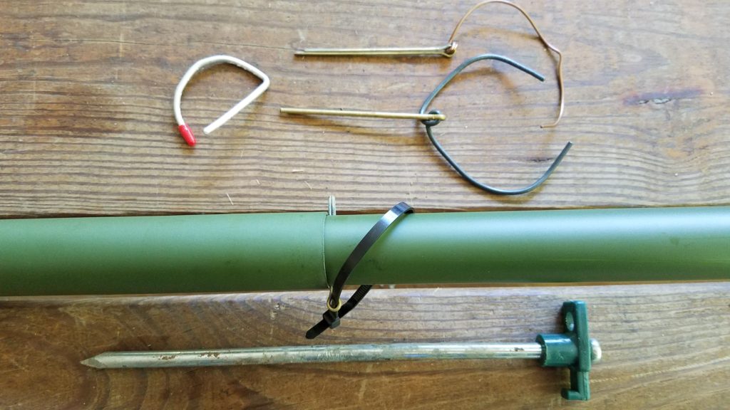
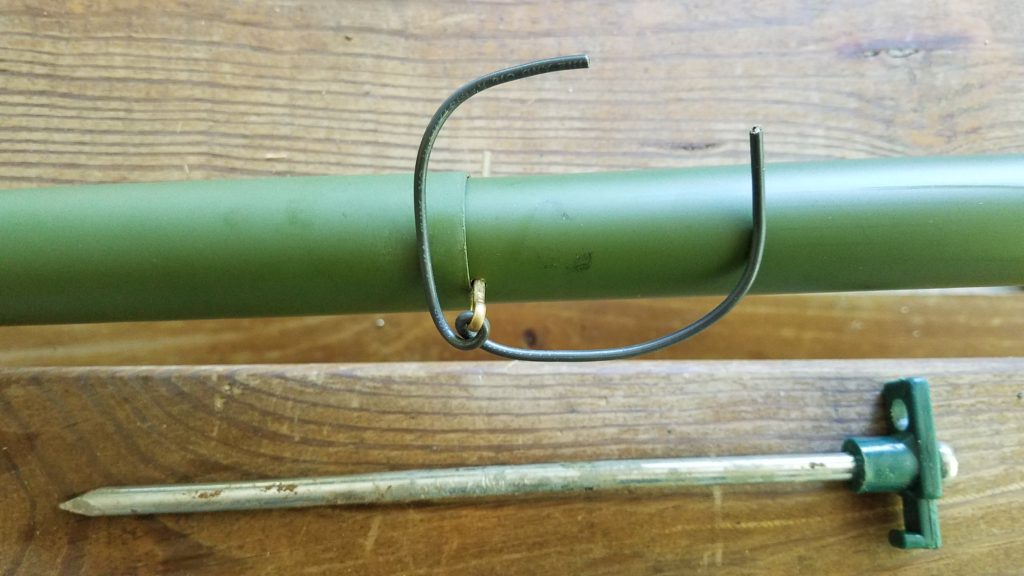
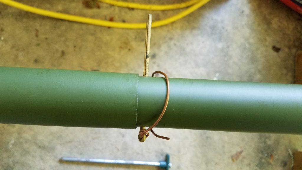
The solution I chose was to drill the mast and use 1/8 or 3/32 cotter pins at the bottom of sections just above where they rest when extended. The pin rests on top of the next lower section, so no problems trying to align holes through two sections. Saving another 1000 words……
A section of mast extended showing position of pin, which goes through only the base of the single section.
Over the past 10 years or so I have acquired a few additional masts. Primarily to have the ability to deploy more than a single antenna, but also as redundant or spare masts. [Two is one, one is none.] These additional masts include the 12m Spiderbeam pole, both a 28 and 32 foot mast from Jackite, a 22 foot mast that was marketed as a flagpole, and several Shakespeare 20 foot Wonderpoles. The Wonderpoles are used mostly to elevate the ends of the dipole legs when it seems appropriate(mostly constricted spaces).
The mast from K4TMC has seen the most use over the last decade. It has a good combination of stiffness and flexibility for its length. I had my doubts about drilling holes for the cotter pins, but the mast has been deployed for extended periods with little signs of anything more than minor cosmetic damage. The Spiderbeam mast seems to be much more flexible, which tends to negate is useful length as a center support for dipoles. Both Jackite masts seem to be the most rigid of the group, but I have used these less than any of the others – they are relatively new buys.
The disappointment of the group for me is the Spiderbeam mast. Its flexibility requires guying to keep it from noodling with the weight of a very light weight 40m dipole made of 18ga wire. Best practice seems to be best to attach the feedline to the mast for any of these type masts, but absolutely essential with the Spiderbeam. My Spiderbeam pole also becomes difficult to extend to its full length the more it bends, although that does help keep it from spontaneous collapse. Also more difficult to deploy in heavy wind at the beach due to flexibility, common to all but more pronounced on the Spiderbeam. The other masts are more self supporting when used with the auger bases. This may indeed have more to do with their overall shorter length, and the spiderbeam masts are indeed intended to be guyed by the manufacturer. I would prefer not to use guys to save time, but in several excursions I was unable to use the full length of the Spiderbeam mast sans guy lines. Even with guys the Spiderbeam pole had excessive droop in high winds oceanside, so the additional time required did not seem worth the effort. Taken all together the Spiderbeam mast was not taking my dipole significantly higher than shorter masts.
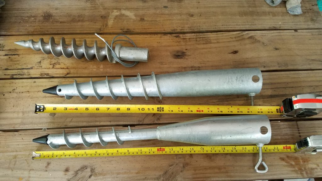
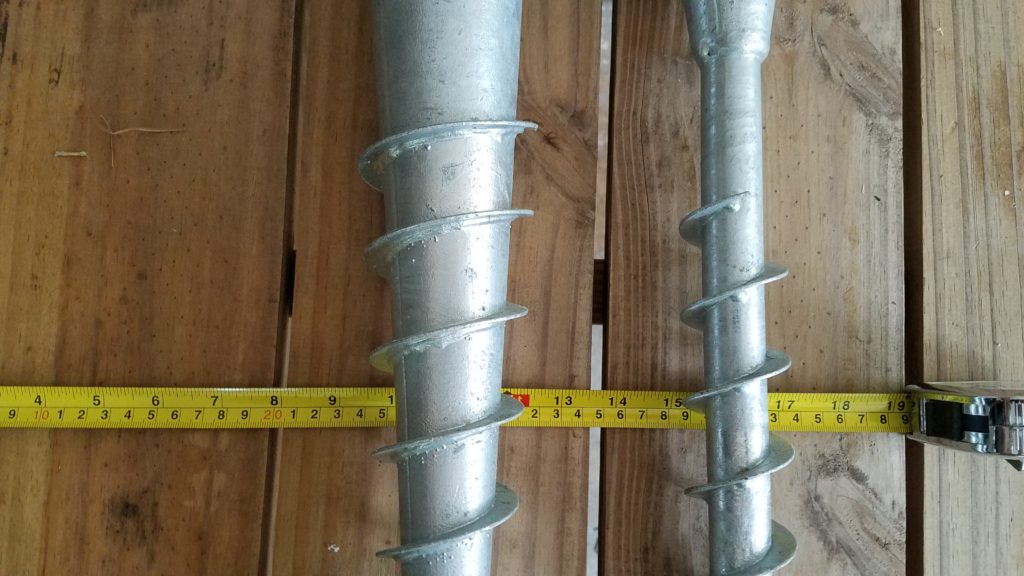
Auger Bases? Why didn’t I think of that? : The other divergence from the norm is my use of these auger bases. These auger bases are items I have scrounged from different sources. The first pair of them I obtained from Harbor Freight in the early 2000’s, where they were being marketed as beach umbrella stands. That source disappeared soon after my purchase. A second group of smaller augers[NOT pictured below] are marketed as “Aussie Augers”, but needed modification to use with the fiberglass masts(unless you don’t mind removing the end caps from the bottom).
These augers pictured below were available via Amazon in the US in 2019. They work extremely well in sand. They are heavier gauge material than the Harbor Freight versions. The larger tapered base is my first choice for sand and seems to be the strongest. It would also work anywhere with a deep layer of loam or sandy topsoil. The base with the narrow welded on auger is more useful where the soil is less friendly, with stone or tree roots. I use the narrow base in my home yard, which is chock full of quartz stones and tree roots. It sometimes requires multiple placement attempts, but seldom takes more than a few minutes to install. For areas with no topsoil, shallow stone, or mountains, this solution might be less than ideal. The other caveat is leaving a hole in the deployment area.
Both bases are about 60cm in length(22 inches) and have a 60-61mm throat width(approx 2-3/8 inches). This is just barely wide enough for the Spiderbeam mast to fit without removing the base cap. All of the other masts are a bit smaller at the base and fit in easily. The large base has a depth about 178mm(7 inches) and the larger a depth of 127mm(5 inches). FWIW, with the smaller diameter masts I often insert a section of 2″ PVC into the base as a bushing sleeve, and the mast into the PVC bushing section. Large tapered base at Amazon [American Ground Screw Model 2] Narrow welded base at Amazon [American Ground Screw Model 1 with Cap ]
Two different types of auger bases for use with telescoping masts by W4KAZ
Two different types of auger bases primary difference is size. The auger on the left has threads down a tapered shaft. On the right, the auger shaft is a uniform width of tube welded onto the top section. The usable depth on the left auger is also about 2 inches more than the one of the right.
I don’t expect I have been the first to go down this less traveled path but have not seen it documented elsewhere. So some photos above for reference. I drilled 9/64 holes in the bottom of each nested section, just ABOVE the joints, and use 1/8 cotter pins.
My 10+ year old mast from K4TMC has been deployed numerous times. There is still only minor wear to the drilled holes, and zero cracking or vertical splits. YMMV. Caveat Emptor. An additional tip would be to have spare pins, and pins in at least two lengths. The bits of wire are used to keep the pins from vibrating loose in the ocean breeze. The also are used with coax to keep the feedline close to the mast. Generally I tape the feedline when using twinlead.
The choice of feedline is made on deployment depending on the distance from the antenna to the operating position. I use LMR240/RFC240 for the feedline drops when the operating position is close to the antenna, and 300 ohm ladderline from DX engineering for long runs.
By w4kaz, created on 2018.07.22 at 11:58:16 | last changed on 2018.08.27 at 17:39:43 |
The normal group of Field Day scalawags were in the wind for 2018. N4GU was uncertain if the QTH from 2016 and 2017 would be available. N4YDU took up N9NB’s offer for FD at Ted’s QTH in VA foothills. I was also kindly invited, but decided that I didn’t want to drive quite that far, despite the nearly ideal location. I do love me some VA mountains.
For 2018 I took exit ramp #3, and went with the backup backup plan. Operated 1B at a campground near Wilmington NC. A nice easy drive, with a couple of easy on/off stops along the way to stretch out the body parts complaining loudest. That made the drive tolerable.  Also made it into a mini-escape, leaving home QTH on Thursday with a return on Monday morning.
Weather conditions[i.e., heat] soon had me thinking I’d have been better off in the VA mountains, but after acclimatizing to “swamp butt” conditions, it was fine. When I sweat enough to remind me of living on the South coast – its pretty darn sticky. Usually not quite so bad in NC, but it happens enough to know to be prepared. Lots of water and gatorade. Thursday afternoon was the worst of it though.
Friday morning was spent doing a bit of unrelated recon. Friday afternoon I laid out the antennas and supports, and some more unrelated area wide explorations. WX on Saturday dryed out some, and there was a nice breeze that picked up from the start of operations though early evening. Never a drop of rain, just temps and humidity in the 90’s. Just like being back in good ole Bigg Swampy(SE Louisiana).
Antennas:
2018 was a time to test some antenna ideas. I built a 2 band triangular yagi for 20m/15m, based on article by Herb,N4HA as published in June 2018 QST. I kept to the published dimensions(mostly) but fashioned the driven element(s) from 300ohm ladder line. For supports I used a mast from Henry, K4TMC as the support for the drive element/apex. The tails sloped down to connect to the reflectors, and those ends were supported by 2 masts cobbled together by combining a Shakespeare Wonderpole on top of a section of 4 foot mil surplus mast.  Simple, and easier than I expected. This antenna was fed with 300 ohm ladder line run to a tuner rather than coax.
40m was a simple inverted Vee supported by a Spiderbeam 12m telescoping mast. Note: Simple does not mean “easy”.
10m was an afterthought. After struggling with the 40m dipole-that-wouldn’t, I had a relaxing breakfast and gave some thought to 10m. Had plenty of time, so may as well. To get on 10m I made a dipole by cutting a couple of equal 8.5 foot lengths of wire and constructed a “FD style” center insulator from a pair of cable ties taped together. Used a “composite” feedline – a ladderline drop to a 1:1 unun and a short coax run into the tent. I had a length of ladder line about 25 feet long so the 10m dipole was up about 23 feet.  At the end of the ladder line at ground level I plugged the ladder line into a 1:1 unun, and ran the last 30 feet or so into the station with coax. From start to finish this antenna took about 30 minutes to put up, including cutting legs and twisting it all together.
No antenna at all on 80m. Decided I’d have enough business on 20m & 40m to keep occupied, and figured on sleep rather than a night of 80m T-storm QRN. 😮
Now, about that 40m Vee. The antenna that would NOT. Still not certain where the problem was, but it had an issue in one of the feedlines somewhere[update-think one of the legs has broken wire]. Far too much time was wasted raising and lowering the antenna trying to debug the issue. Lesson1: Always have an alternative.  Lesson2: Don’t dick around debugging when you have the alternative at hand ready to go. Lesson3: Save debugging for down time. Lesson4: Read Lesson1 and Lesson2 until they really sink in.
Operating:
Once the CQ’s started, there were plenty of QSO’s to log. Saturday was a bit slow at first, but I got a better rhythm in the evening. Was tired though, and sacked early, including a 45 minute nap at 5pm in the nice cool breeze that came up. Also got up early Sunday, 5am-ish.  Sunday morning was quite a bit of fun, right up until my keyer interface died around 11am. So I finished the event with a bit of lackadaisical SSB, mostly S&P.
Camp:
The Cabelas tent goes up easily. My only regret is not getting one of the larger sizes. It has room for setting up a table for the station and also for a cot along the opposite side. But it is a bit cramped. Next time I do this I think I will use a screen tent for the station and the tent just for snoozing/bad wx. Also, the ideal site would allow for the tent to use an overhead spike support and avoid the need for the center pole.
Overall a big win. Keeping the ants away…..the real challenge!