The 2025 IOTA was run from one of the cabins at Cape Lookout(Iota NA067 and Pota US-0683) using the call sign N4C. Ops N4YDU and W4KAZ. N4YDU made the decision to tag along for the 2025 Iota contest outing. As always, having a world class operator means the radio will get a lot more actual use than it would have had I been alone. I am betting the log accuracy will be better too, at least for the YDU QSO’s. 😮
After returning from Field Day a month earlier I gave a bit of consideration to canceling the IOTA trip to Cape Lookout. Then decided to go ahead and keep the trip as scheduled. I’m not even sure if I nudged N4YDU or he asked if I was going, but after the first contact I made sure Nate knew there was plenty of room if he chose to make the trip. And plenty of operating time to fill if he chose to do it. “Highly motivated operator” is not a label I would ever apply to myself. My own interests are more about seeing what works and what does not.
WX es environmental konsiderationz
As luck would have it the weekend of the contest brought a few days of clear weather. The “weather tax” this time around was sticky-hot-humidity. Not only was the temperature elevated, but the wind was very mild for the NC outer banks. There were a couple of points where we even had dead air, drawing out the biting kritterz of the insecty sort. Gnats and green-head biting flies. At one humorous point, a literal cloud of gnats. Bitey-bitey!
Spraying the cabin window screens helped limit the gnat incursions into the cabin. Ants were present but thankfully not into the food and refreshments. Battery fans provided some moving air overnight to help permit sleeping in the ick. Even the rudimentary cabin was much more comfortable than setting up in and living in a tent in the style of a tropical DXpedition. Window screens, running water and a flush toilet beat the shit out of roughing it like the days before industrialization.
Antennaz? We are doing WHAT for Antennaz?!?
Maybe that’s how the conversation got started with ‘YDU, because I know I texted him to see if he had ever dorked around with a 40m OCF dipole. I had already decided to experiment using a 40m OCF fed directly with 300 ohm window line run back to the shack into a 4:1 balun, and a short coax jumper from balun to a tuner. The second antenna was to be a 59 foot doublet(K2AV suggestion from 2010) from FD and (failed)WPX. Once YDU jumped aboard ship he verified function of his butternut vertical and that was added to the list. For backups I had along a selection of other things(trap dipole, EFHE, linked dipole, etc) that we could have used in a pinch.
The OCF and the doublet were set up favoring Europe, parallel to one another and about 80 or 90 feet apart. The modeling on that seemed ok, but in hindsight I doubt I would do it that way again. The vertical was deployed in a mostly clear area to the NE of the doublet. The wire antennas were supported by 30 foot telescoping masts that are self supporting when mounted in the screw-in ground anchor bases. All of the exterior work got done Thursday afternoon after catching an empty slot on an earlier boat than the 2pm ride booked.
Since the OCF was fed directly with the 300 ohm window line and the balun located just a coax jumper away from the radio, I presume without actual measurements that the feedline was radiating in random directions along with the antenna itself. Probably not ideal, but the QSO’s got logged anyway. In practice there was little difference between the doublet and the OCF, while the vertical showed occasional improvements on some signals. FWIW the doublet had marginal less static/white noise/QRN than the OCF.
Radio? Where the hell is the stupid adapter? Why is this an RCA jack?? WTF????
Setting up the station was an exercise in “where is that cable”, since the last couple of times had been with the K2 instead of the K3. Everything needed was there…somewhere. The Elecraft K3 was used. Logging under Writelog, which took YDU a while to adjust to his preferences. The wire antennas were both routed from their baluns to an MFJ tuner that was used as an A/B switch in the tuner bypass positions. The tuner’s antennas routed to the K3 antenna one position and the vertical was routed to the K3 antenna 2 position. The K3 internal atu was used for matching to the wire antennas, and not generally needed for the vertical. After pulling a bad set of headphones everything was working. Too easy. It is NEVER that easy.
Contest? There’s a Contest today?
N4YDU started out hot from the gates and chased mults and called CQ. 15m was the big surprise for me, as the 15m band has seldom been open during this contest for this QTH over the past several years. The low USA activity levels make the first 8 hours of the contest somewhat of a challenge. The EU stations tend to concentrate on working other EU. Since the Cape Lookout QTH is also a POTA entity, for my part I alternated calling CQ for IOTA and POTA. The self spotting rule change allowed us to post spots in the POTA system. This resulted in some decent rate hours that have been really dead in the past. I hit 15m and 20m hardest for POTA, and neglected 40m entirely. Probably left a lot of POTA Q’s on the table by never getting to 40m.
As the afternoon grew longer it sounded like 20m was ready to open pretty well to Europe, so I wanted YDU to have a shot at the possible higher rates. Also better to have the better op on the radio when 40m opens. While it was nothing like a major contest rate wise, the best rates we had were centered on local sunset on 40m. YDU pulled the plug for the evening around 0400Z. The early morning/local sunrise hours did not produce any JA, KH6, ZL or VK, much to our disappointment. 80m over-performed beating out 10m by 16 QSO’s and 4 mults.
The Good, The Bad, and The Ugly
The Good: As always, enjoyed have N4YDU along for the trip. We had a bit more time for setting up as we were able to catch and earlier boat to the island than the one scheduled. That alone gave us an extra two hours to set up antennas and such. All of the antenna systems functioned as expected and no repairs/redo’s/debugging was required on the antenna systems. The radio systems were “mostly” ready to plug and play, but I will need to repack/review/reequip the radio set ups with the goal of having each radio packed individually as a stand alone unit. WX goodness was complete lack of thunderstorms, a rarity over the past 10 years.
The Bad. The worst part was weather related. Although we were spared any electrical storms, that was all due to a high pressure system sitting over the region that also drove the temps into the mid 90’s (95F/35C) with the associated oceanside high humidity. Just like being in Louisiana again! Except I’m no longer acclimated to the norms of S. Louisiana weather. Nathan took to dunking his shirt in ice water to get some relief. Normally Cape Lookout has a consistent breeze blowing that helps mitigate the heat, but we caught a couple of spells of nearly still air.
The UGLY: Bugfest 2025. The other downside to the still air is that it gives the biting flies and gnats(“Gnatzi’s”) freedom to roam. Just like being in Louisiana! Humorous anecdote reserved for in person grinz.
Addendum(2025-08-09): What Next?
The question naturally arises: “Is this 2025 Iota antenna plan how I would do it again?”. The answer that intermediately comes to mind is “NO”. But that would be the case just out of the curiosity of trying something new. If I were to deploy the same antennas again, I would have put the two wires at right angles based on how similar they functioned this year. Also, after some more research and modeling, I think the OCF needs to be rebuilt. It seems like feeding at 40% point makes more sense, giving a better match on 15m and 10m while keeping 20m and 40m at a low swr. (TO BE TESTED, 40m OCF with 27.5′ and 41.25′ legs[8.38m and 12.57m]). LINK: “Off Center Fed Antennas” W3TB youtube presentation, April 2023 WCARES. Also thinking about how and 80m OCF would fit into the favorite Iota QTH. Then there are the permutations and combinations yet tried(OCF and EFHW, doublet and EFHW). The grass is always greener, aina?
3830 scores for Multi stations and band breakdowns
POTA Results
POTA hunters came in for the Q’s, and there were 42 P2P Q’s confirmed so far in the POTA system. Just guessing, but it looks like about 150 to 200 Pota hunters checked in, and that is probably a conservative estimate. Thanks fer the Q’s hunters!
Pota from Calo this year:
Screenshot 2025-08-07 – POTA activations from US-0683, Cape Lookout National Seashore
By w4kaz, created on 2025.03.15 at 19:27:17 | last changed on 2026.05.04 at 20:52:25 |
Looking at a few of the promo vids folks have posted so far about the Pota33H mast I decided to take a chance on it and the order arrived late last week. On first look I thought it might not be long enough to stretch to the 30-ish feet, but I underestimated the strength of the carbon fiber. For its short length it has a lot of sections inside, and the top section is about 1/2 inch diameter tube. Thicker tubes are stronger than thinner. The carbon fiber provides a lot of strength in a much thinner level of material, so it should be just fine. I expect it will have less flop/droop than any of the fiberglass masts. But the folks who got it made should be happy, it seems to check all of the design goals any backpacker might have for compact, lightweight, and strength.
It did have a couple of caveats for my own uses. If the mast were a full 48 inches I would like it better, but it was designed for its short collapsed length. The second caveat is more of an impact for my own purposes. The base piece at the bottom of the mast is heavy duty, and quite thick. The end cap is thick and sturdy. So thick that as delivered it is just slightly too large to fit in one of my favored mount methods, a trailer hitch post holder.
The end cap from the pota33H after filing is about 60mm diameter. It fits into one of the hitch mount post supports, but not the other.
The hitch mount that does not accept the Pota 33 mast appears to also be about 62mm diameter. Perhaps it is out of round? Thicker walls? Will need the micrometer to find out, the two different pole receptacles appear to be the same size to eyeball mark 1.
The hitch mount that accepts the Pota 33 mast is about 62mm diameter.
Pota 33 base fits for this hitch mount after a bit of judicious filing
Pota 33 base is too fat for this hitch mount
The truck hitch receiver with a step extension that supports the telescoping fiberglass mast. The mast du’jour is the Jac-kite 31 footer. Plus assorted extra junk in the truck bed.
After trying the mast in both mounts it was clear it was very close to being able to function in one of them. After a few passes with a file around the widest part of the pota33h’s base cap, it was able to just barely slide in to the hitch mount. That will make deploying portable a bit more convenient. Kinda hate putting the file to a massage brand new sort-of-pricey mast, but WTF. Not like I was sending it back anyway.
Also, the pota33h should be FB for use in the screw in earth anchors I use for the beach side deployments. As long as it works with those its worth trying.
The unknowns now are: What it will do with a real antenna attached? Will the friction fit hold in the wind? Will the friction fit hold an antenna without collapsing in the 20 knot winds common on Cape Lookout? Will the carbon fiber be better than fiberglass when stressed? Will the thin wall carbon fiber tubes crack and split, compared to fiberglass more or less likely? Will sand prove to be a bigger problem for this mast than others? Will it really be less floppy than its fiberglass predecessors? Will sand cause it issues? Will it have difficulty being lowered after a roll in the Cape Lookout sand? TBD…soon!
By w4kaz, created on 2025.03.14 at 17:14:43 | last changed on 2025.03.14 at 18:15:48 |
This year for the NC QSO Party I activated three Pota entities in three different counties. US-6909, Harris State Game Land(WAKe county), US-6920, Lee State Game Land(LEE county), and US-6916, Jordan State Game Land(CHAtham county).
After Action Photos
Did not take any photos during the event, but the morning after. The extension on the hitch mast support allows dropping the tailgate with the antenna deployed. On my last vehicles(a 4runner and Jeep Cherokee) I also had a front mount hitch, which I prefer to use for the mast. So far the only front hitch I have found for the Sierra hangs down too far. The ground clearance on the Sierra 1500 is too already low for my preference, only about 9 inches. Begs for a 3 inch lift. The “radio mount” in the vehicle is comical, a 5mm plywood board resting on a jack stand in the front and taped to the console in the rear, with the radio “secured” with more painters tape to the board. Hmmmm……sketchy, but functional.
The truck hitch receiver with a step extension that supports the telescoping fiberglass mast. The mast du’jour is the Jac-kite 31 footer. Plus assorted extra junk in the truck bed.
The high tech radio install for the 2025 NC QSO Party. The battery is behind the radio sitting on the “parts-n-spares” tote. MFJ tuner in passenger seat on radio storage box.
STATION
The station du-jour was the FT-891, logging with a kludged writelog half assed set up. For whatever reason Writelog was not flagging dupes, so I was trying to look them up manually while S&P. Mostly just went S&P while trying to find a clear frequency.
Used a telescoping fiberglass mast at all three sites, which showed more droop than expected. The telescoping mast was supported in a hitch mounted pole support with the base of the mast resting on the ground. The antenna was a 58 foot doublet fed with 300 ohm ladder line into a 4:1 balun, with a short coax jumper into an mfj-949 tuner, radio set at 100w. Logging on a laptop running Writelog, which could send frequency changes to the radio but was not polling and keeping the log updated when spinning the dial on the radio. At the third and final stop the antenna was modified to extend the length to 90 feet for better use on 80m. Power to the radio is supplied via a 100ah LifePO4 stand alone battery. Radio conditions seemed excellent for most of the day. The broadcast stations on 40m became troublesome, should have moved to 80m late. Lack of sleep kicked in late though, and I bailed with an hour of time left on the table.
The Day
The day started out at US-6909 on frozen ground. Arrived a bit early to set up before NCQP startup, but was running late anyway. Wound up doing only SSB. Could not get any results on 20m, so moved down to 40m to work more locals. Ran into that days’ only problem when the keypad caused problems with the radio. More on that later….. In the meantime, had a decent time at that location.
Moved on a few minutes earlier. The second location at us-6920 was in full sun, but had the best rates of the day. As the afternoon wore on I began to miss the freezing weather from a few days earlier. Operating in the vehicle was a bit warm under the clear skies with temps almost hitting 60 outside. But the 20m pileup of Pota ops was worth the sweat.
The final location, US-6916 was a good choice logistically, but the band was crowded and it felt like folks were not taking into account the park and county had changed. Note to self: Game lands get REALLY dark, bad idea to misplace the flashlight.
Musings In-No_Particular-Order
Generally, it was a pretty fun outing. I’m torn between using Writelog, which I really like, but does NOT FUNCTION PROPERLY with my FT-891, or finally switch to N1MM which I generally HATE WITH A PASSION. Suckage either way, although the FT-891 itself is more than likely the point of failure. I can probably get over my N1MM hate fetish, but the ft-891 would still be a problem due to the dread “Cat Control Tick”. FT-891 Tick worse than N1MM which is worse than Writelog not working with the 891. ??PAPER LOGS???
So in this case I used Writelog anyway, and resigned myself to fucking up the log. I like Writelog, and I like the ft-891 as a radio. Maybe N3FJP is the solution, I already have the license, I like it better than N1MM, and I had it working with all of the radios(ts-590/K2/K3/ft-891).
Other minor issue…..somewhere Saturday loading the truck I misplaced the FH-2 keypad. WTF!?!?!? I had the home brewed keypad, so I used that, but it was causing it own issues. Like for some reason when trying to record messages it was changing the radio frequency instead. NOT GOOD. The temp solution was to use the radio controls to record the messages, and forget about customizing the radio message memories on the fly. I hope the FH-2 keypad turns up when I ransack the vehicle tomorrow.
Other issue….I gotta learn how to pare the gear down. A correctable personal deficiency. Not EASILY correctable, but correctable. 🙁
Observation-1 ….The 58 foot doublet K2AV came up with several years ago for use in the IOTA contest is a really good general purpose antenna for 40/20/15/10. It was originally designed to allow the Elecraft K3 internal tuner to find a match, so it is a piece of cake for an external tuner. At the last stop I added legs to increase it to a 90 foot doublet to allow using it on 80m/75m, and easier match for the tuner. The shorter length models well showing useful patterns on all four bands and matches easily. Use the K3 in the car? A possibility.
Observation-2 ….The antenna used was constructed of 16ga wire, The mast droop is substantial especially with the longer legs. Time to try 18ga wire again? The 26ga stealth wire?
Results:
NORTH CAROLINA QSO PARTY
Call Used : W4KAZ Last County Ran : CHA Callsign(s) of Operators(s) : W4KAZ Entry Class : Single Op – In State
I have followed the North Carolina QSO Party Rules ALL Operators must sign clearly, including callsign Signature(s): ___________________________________ Date: ______________
MULTIPLIERS WORKED:
ALA ALE ASH AVE BLA BRU BUN BUR CAL CAM CAR CHE CLA CLE CUM DVD DUR FOR FRA GUI HAR HEN HYD IRE LEE LEN LIN MAD MCD MEC MIT MON MOO NEW ONS ORA PEN PEQ PIT RAN ROC ROW RUT STA STO SUR TRA UNI WAK WAT WIL YAD CT MA NH RI VT NY NJ DE MDC PA AL FL GA KY SC TN VA AR LA MS OK TX MI OH WV IL IN WI KS MN MO SD NB ON You have also been credited with one mult for DX
By w4kaz, created on 2025.01.06 at 10:01:53 | last changed on 2025.01.09 at 16:30:42 |
After a detour to building the 2 band trap dipoles using rg-316 type coax, the worm turned. The failure of a couple of the coax trap antennas due to incomplete sealing and weather proofing the coax became a problem. The antenna at home failed. Two of them. Then the antenna being used for portable ops failed during the 2024 NC QSO party. In the meantime, the home antennas built from coils and capacitors for 40m/20m are still in use 4 years later with no change in resonance points.
Rather than continue with a seemingly fragile system it was time to revert to the coil-and-cap design. Avoiding the cap failures previously experienced on the 10m/15m antenna is addressed by using caps with low enough values to be appropriate for the 10/15 version. So a supply of the TDK ceramic caps was laid in. These caps have 3KV and 6KV ratings. Parts#810-CC45SL3JD080DYGN (example is 8pf SL 6kv) from mouser. TDK Data Sheet for Sl ceramic capacitors.
For the 10m trap a value of 10pf was used, with 16 turns of 18ga stranded wire tightly wound on a 1 inch diameter piece of fiberglass tube. (calculated inductance is about 3.25uh) This originally resonated about 27500, but crept up after taping and sealing to 28000. Decided to roll with them as constructed. These may be fragile, too fragile for portable use, as 18ga wire was also used for the connections. NOTE: USE LARGER GA WIRE FOR CONNECTIONS.
The “tricksey” part discovered previously is that using caps with a large enough reactance on the upper band helps them survive by limiting the current actually flowing through the capacitor. At the 100w levels the voltages are less of an issue than the current handling. Using parallel-series combinations can also help, depending on what value caps are available.
The downside is that the inductance value to resonate the trap for 10m becomes relatively large. This makes tuning the antenna for the 15m band “tricksey”. The 15m tail is short, maybe 15 inches from the relatively large inductance used in the trap. When trimming, very small trimmings move the 15m resonance quite a bit more than on a normal 15m dipole. The good news is that the 10m band is only very slightly effected by trimming wire on the 15m side of the trap. The 15m tails needed to be replaced and re-trimmed after trimming a 2 inch bit of wire moved resonance from 20.85mhz to 21.65mhz. oops. SMALL SNIPS FOR 15m tuning!!!!
After trimming, the 10m/15m antenna is good from 28000 to 28750, and also covers the entire 15m band. STOP….DO NOT TRIM AGAIN!
The 20m/40m version is built with a trap resonance at 13.65mhz. The 20m legs are approximately 15ft long. The 40m legs will be about the same. (?actual measurements?) Total antenna length of about 60 feet.
Both of the 2019 home 20m/40m trap dipoles can be easily matched with the Kenwood TS-590 internal tuner for use on 10m as well, which provides options. Worked JA’s on 10m using the 20m/40m trap dipole several times now. The new version for the 20m/40m portable does NOT tune on 10m, probably because of the different value of capacitance/inductance used, or maybe because the new antenna traps resonate at 13.65Mhz instead of 12.5Mhz. The new trapped antenna covers the entire 20m band, with the highest SWR of 1.5:1 at 14000-14015. The 40m band is below 1.5:1 SWR from 7000 to about 7250, with the swr going to about 2.3:1 at 7300.
(For future testing, add turns
Using the new 1 inch o.d.(~25mm) fiberglass form material as the coil form and the TDK capacitors:
Freq———Capacitor——-–# turns calculated——#turns actual——-
27.7Mhz—>10pf————->12 turns (approx)—–> 12 turns, 28Mhz(use 12.5?) (calculated inductance of 3.25uH as constructed)
20.66Mhz–> ?????
13.75Mhz—> 34pf————>16 turns —— ——–> 16.5 turns, 13.65Mhz (calculated inductance 4.04uh)
6.75Mhz—-> 16.33 turns
By w4kaz, created on 2024.03.18 at 12:52:01 | last changed on 2024.03.18 at 13:37:30 |
A really cool RBN mapping site:
Check out the work of HA8TKS. Good format, centers an azimuthal projection on the searched call sign with lots of options. Lots of options to play with, can be used to list the spotter station or see stations that are spotting a caller.
[edited for links and notes, 2023/07/15] The original trap dipoles were constructed using coils and caps. Using Rg-58 for the coax style trap dipoles was rejected because of the weight and size of rg-58 coax traps. Using RG-58 defeated the primary goal of making the antenna as light weight as possible.
Somewhere I picked up the notion of using rg-174 or rg-316 type mini coax to make the traps. It looks like the voltage ratings on the rg-174 is higher(1100v rms), so that was chosen for the first experiments. If luck holds out, the tiny coax will be sufficient for use on the dipole traps for a full 100w CW. Using the smaller lighter mini coax will allow for lightweight construction from easily available materials that can be easily supported using telescoping fiberglass masts like those available from Spiderbeam, MFJ, or Jackite. i.e., perfect for portable, field day, rover QSO parties, or POTA/SOTA.
The trap calculator program hosted by KC1KCCgave me some starting numbers to work with, and actual trap measurements came out quite close to the calculated values. [alternate calculator at K7MEM]  The traps are built with the coax coils wound reasonably tight to the form, and the coils were taped down with electrical tape prior to taking measurements. These are all wound on small sections of the same sort of plumbing drain tailpieces that are 1.5″ od (38mm od). (e.g., in the US available from Lowes or any hardware store selling plumbing supplies.) The table below are of traps as built and tested with the nanovna.
frequency
turns rg-174
27.7
3.33
20.66
4.33
13.75
6.1
6.75
10.3 [calculated]
Update, 2024-04-04
Received a new 1 inch o.d.(~25mm) form material that is lighter. testing.
Freq———–# turns calculated——#turns actual——- 27.7Mhz—>5 turns (approx)—–> 5 turns, 24.8Mhz(use 4.5?)
20.66Mhz–> 6.25 turns————> 6.25 turns, 19.65Mhz(use 6)
13.75Mhz—> 8.75 turns ——–> 9 turns, 13.5Mhz & 13.7Mhz
6.75Mhz—-> 16.33 turns END 2024-04-04 Update
Test Antennas:
The test antennas were built for the CW segments of each band. With the best SWR centered on the xx.070 area it will probably give enough coverage for both CW and SSB operation without a tuner. An 80m/40m version will require tails for 80m adjustments.
Testing of two antennas was done before the May 2022 CQ WPX CW contest. The 20m/15m version tuned easily….after I figured out I was working on that instead of the 10m antenna. Read those labels, because at least I had them labeled properly when they were built several weeks earlier. The 10m/15m version also tuned easily.
[aside: the 15m/20m trap is now in service as the skimmer station antenna, after a recent storm broke the 160m inv-l]
Although I missed the WPX contest, I soon got a chance to do antenna testing at 100w levels.  Both antennas handled the power easily with no signs of SWR rise. Both were tested at 10 seconds, 30 seconds, 60 seconds and five minutes of CW key-down.
Hoping for good conditions in FD to allow testing of the 10m/15m version. Sunspots, do your thing!
[2023-07-15 additional notes] The coax traps began showing swr problems on 10m after a few months in the weather. Expecting this to be a problem with water intrusion. testing the use of WeldBond glue as a sealant. [alternative….Elmers ProBond] Also testing the adhesive as a sort of q-dope to seal the coils on the form.
Adding a linked in tail to the 20m/30m EFHW turned out to be about as easy as you might expect. The 40m EFHW was tuned for 7.100. The other bands could be easily matched by selecting the best match via moving the transformer tap.Â
The links at 20m and 30m will allow a lot of versatility at the cost of lowering the antenna to connect or disconnect the links. Likewise with the transformer taps. So a bit of footwork is the tradeoff for multi-banding. But its not just the band changes. Judicious configuration choices allow the possibility of multiple choices of radiation patterns.
BAND
TAP
Best SWR
SWR range to expect
40m
8.5:1
7.1(1:1)
Entire band, (1.3–>1.6)
30m(j)
8.5:1
10.25(1.6:1)
Entire band, 1.6:1 with wire drooping
30m(j)
8.5:1
10.1(1.3)
Entire band, 1.3:1 with wire pulled taut
30m(j)
7.5:1
10.3(1.4)
Alternate tap,1.4:1 with wire pulled taut
20m(40m-tail)
6.5:1
14(1.4)
Entire band 1.4–>1.6)
20m(no 30m/40m tails)
8.5:1
14.025(1.4)
Entire band favoring CW section
15m(40m tail)
4.5:1
21(1.1)
Entire band 1.1–>1.8
15m(j)
4.5:1
21.010(1.4)
Entire band under 2:1(wire drooping)
15m(j)
4.5:1
21.010(1.0)
Entire band flat with wire pulled taut
10m(40m tail)
6.5:1
28.0-29
Entire band with tap 3 , 2 or 1
10m
6.5:1
28.000-29.25
28.00 thru 28.800 under 2:1(swr 1.2:1 on CW)
10m
8.5:1
28.00(1.4)
28.00 thru 28.75 < 2:1(swr 1.4:1 on CW)
*note1: “40m tail” implies both 40m and 30m links are attached, other settings are for the 20m/10m as 20m efhw or 30m/15m as 30m efhw.
note2: The transformer taps are numbered 1-5, where tap 1=4.5:1, 2=5.5:1, 3=6.5:1, 4=7.5:1, and tap 5=8.5:1 turns ratios. corresponding impedance values would be 1013, 1513, 2113, 2813, and 3613 ohms.
note3: -right click and “view image” to see full size images below
Model Radiation patterns-10m
For the 10m images above, on the left is the modeled current and radiation patterns for the 40m EFHW when used on 10m. The right is the current and radiation pattern for the 20m EFHW used on 10m. Switching requires lowering the antenna to either detach or reattach the link at 20m.
Given the lengths of the wire using a 30 foot(~9 meter) support, either configuration will have a considerable vertical component. The 40m version will add a substantial horizontal component. The vertical components will mimic the horizontal patterns to some extent. But the patterns will likely favor different directions. The differences will surely be modest – maybe enough to be worth testing as options. If nothing else, it may help reduce QRN in some circumstances.
Radiation patterns-20m
For 20m, the radiation patterns might actually be more interesting. The full wave version(from 40m configuration) will present a compressed combination of horizontal and vertical components. The half wave version(20m) configured with most of the antenna vertical will have a mostly vertical component with the 30ft/9m support. This may be a fun experiment in a field day operation. maybe worth the effort of switching the links
On a whim I decided to wind a transformer using two FT-140-43 cores. I went with the same 2:1 ratio as the first transformer. SWR testing using this second version showed that all transformers are not equal. The SWR readings taken using the new transformer with the antenna wire as it was trimmed with the larger transformer did not have similar results. It turns out the new transformer would require re-trimming the wire lengths to bring the 40m band into the same SWR curve. Since I had the 80m coil&tail attached using .250 quick connects, it was easy to add wire. Doing that allowed bringing 15m and 10m to good matches. 20m also found a sweet spot but only on the 6.5:1 tap.
New Version?
Without re-tuning the wire no good matches were obtainable on 40m. Instead of making any permanent changes to the working 40m loaded antenna/transformer combo I am making a different wire based on a 30m wire length. It will include a quick connect to allow the antenna to cover 20m by detaching the section of wire beyond the ~34 foot 20m wire length. That will provide an antenna capable of 30m/20m/15m/10m. This may become a simple way to add a permanent 30m antenna in the w4kaz antenna farm.Â
Maybe I get ambitious and add a second link to include 17m, just for grins. Does an easy tune 30m/20m/17m/15m/10m antenna sound good? One could just as easily add quick links for each band. Using the antenna as a full wave on the 2nd harmonic provides radiation patterns that might be more useful, but either choice provides a method to cover each band. The initial lost opportunity cost is the need for the transformer. For quick and dirty field construction a simple wire dipole or vertical would still be easiest – but mostly monoband, as fan dipoles can sometimes be difficult to tune.
Future ideas
Thinking about trying a different twist on using the FT-140-43 size cores by pasting three of them together for a transformer, and trying the transformers out with 3:1 turns ratios. I have enough of the FT-140 size on hand to do this but used my last two of the FT-240 size. My first test antenna seems to be a success, so it just need to be put on the air some to get an idea of how it fits in. It is always good to have the option available.
20m/30m Constructed and Trimmed
Using the transformer built from a pair of ft-140-43 toroids sandwiched together, an antenna for 20m/10m is now built. It includes a simple wire tail that can be attached as a link to extend for use on 30m/15m. It should be a simple matter to prepare a wire for adding 40m use. With the 40m wire 15m should be use-able with two configurations, either 30m or 40m. If 15m is open that might add some interesting changes in radiation pattern when switching from a full wave to a 3/2 wave. May as well add a jumper for 17m too(later-much later).Â
TAP Cheat Sheet, 30m/20m/15m/10m
Taps 20m/30m linked EFHW (jumper to attach 30m/15m)
BAND
TAP
Best SWR
 SWR range to expect
30m(j)
8.5:1
10.25(1.6:1)
Entire band, 1.6:1 with wire drooping
30m(j)
8.5:1
10.1(1.3)
Entire band, 1.3:1 with wire pulled taut
30m(j)
7.5:1
10.3(1.4)
Alternate tap,1.4:1 with wire pulled taut
20m
8.5:1
14.025(1.4)
Entire band favoring CW section
15m(j)
4.5:1
21.010(1.4)
Entire band under 2:1(wire drooping)
15m(j)
4.5:1
21.010(1.0)
Entire band flat with wire pulled taut
10m
6.5:1
28.000-29.25
28.00 thru 28.800 under 2:1(swr 1.2:1 on CW)
10m
8.5:1
28.00(1.4)
28.00 thru 28.75 < 2:1(swr 1.4:1 on CW)
*(j)= jumper attached for 30m/15m
Other ideas and observations
LINKING – Thinking about creating a “linked EFHW” out of curiosity. If 10m were reliably open I would pursue the idea seriously. The different patterns of radiation going from 1/2, fullwave, 3/2, 2xfullwave would be fun to work through.
Using taps on the transformer —-After testing with two different tapped transformers, using the taps makes it simple to obtain a good match. More on the air testing is needed, but at this point trying to obtain good matches using a single transformer ratio seems futile.
Different cores = different wire With both transformers I found that the length of wire needed was unique to each configuration. The lesson is to build the transformer and tune the wire to the actual transformer being used. The ft-240-43 transformer pair would not match the wire cut for the ft-140-43 transformer pair. Need to build more transformers to see if a pair of identically built transformers(size and number) will both match the same wire. Best guess is that will work. But don’t expect transformers with different toroid sizes, or different number of toroids sandwiched together to all work with a set size of wire. Be prepared to test or trim.
Wire droop not ideal  Pulling the wire as taut as possible not only shifted resonance slightly, but improved the SWR match on every band.
By w4kaz, created on 2021.04.06 at 21:18:58 | last changed on 2021.05.06 at 22:39:16 |
After a couple of months of dead air time, the W4KAZ skimmer returned to service on 2021/4/1. The basement area housing the skimmer station required overhauling in order to replace the leaky old water heater. After repairs, the project to return the skimmer system to service was delayed by other issues. Foremost issue was lack of ambition to tackle the organization project spawned by tearing apart the shack. Oiy.
Re-Organizing
Part of the re-org was to add in a new shelf rack, and put all of the shelving on casters. The area is also used for general storage. Being able to wheel all of the shelving out into the garage will make access easier all-around.
The skimmer SDR was also found to have a dying cooling fan, so there was some delay acquiring the replacement. Also some of the old input feedline system was replaced.Â
This was also a good chance to downsize the computer system used to run the SDR.  A “new” micro form factor system was acquired, a refurbished Dell i5 in a teeny 8x10x2 box. That’s a huge improvement over the desktop tower sized system previously in use, and the space savings will be appreciated. The new system has a slew of USB ports, but little else. The desktop box will be stored and can be swapped in if needed as a backup.
Skimming System
The skimmer as currently being run still consists of the Red Pitaya used as an SDR, with the 160m inv-L over FCP antenna system. The new Dell system is a Dell Optiplex 3020 micro form factor equipped with a 4th generation i5-4590T processor, 12gb ram, on a win8.1 pro OS platform.  This processor is 4-core/4-threads and runs somewhat faster than the previous platform. On a lightly used band the skimmer is humming along using about 5% of capacity. On a heavy contest this will probably max out at about 20% CPU. Good enough for CW skimming, but probably not too hot for RTTY. Other SDR software has not yet been migrated to the new CPU.
The main reason for the CPU parallel “upgrade” was the micro form factor of the acquired system. Having the computer be the size of a SMALL cigar box is a huge convenience for a cramped shack location. It also sports a solid state drive, which has been the single most likely point of failure for previous CPU’s installed in a somewhat humid non-climate-controlled location. But the size is most important. (That’s what SHE said….)
Whazzup Wit All Dat?
So now that the system is up and running, more shack clean-up and resurrection is coming. Organizing mediocrity out of the mayhem is the plan. But can the plan survive contact with the mayhem? heh – probably not.
Update-20210406
Unexpected crash of CW skimmer ~0800Z 20210406
Unexected crash of skimmrsrv `0800z 20210407 (???)
The first attempts to tune up the real antenna did not go well. I found from the trap dipole project attaching the wires beyond the trap was needed to get the higher bands tuned properly. This worked against me here. With the high impedance on the end fed I was better off tuning the 40m antenna segment without the coil and 80m tail attached. Unfortunately, I wasted a lot of time experimenting/snipping before I decided to detach the inner antenna from the coil.
Once taking that step, I found I had probably trimmed too much off. Tuning for 40m without the coil proved simple enough. After that the other bands were easier too. I was also able to re-attach the coil and 80m tail, and find tap settings and tail lengths to allow operation with good matches on 80m and 20m. With the 20m tails attached 40m operation on the upper edge is possible. With tails 40m SWR was a bit high on CW segment, although possible with a tuner. 10m seemed unaffected by the coil and tail. 15m provided low SWR only with the coil and tail detached, but SWR of 2:1 up to 3:1 with 80m coil and tail.
Antenna Stuff
The coil as wound measured out to 77.5uh, resonant at 3.85Mhz with 22pf of capacitance. It is ~63 close-wound turns on a mystery plastic coil form of ~2 inch diameter, wound with 16ga solid insulated wire. The final wire length in the 40m section is xxft(zz.zm). The 80m tail is xxft(zz.zzm) in length and the portion for ssb(75m) is xxft(zz.zm). To make the choices more flexible for POTA or other portable uses, I have a series of jumpers in several key places.
The first of the jumpers is installed near the feed point. The antenna was trimmed at the feed point for ease-of-access reasons. Since I ultimately decided I had over-trimmed before detaching the 80m coil&tail, it seemed easier to insert a jumper there. This will also allow having an easy method of re-tuning on the fly if it seems necessary in different deployment configurations.Â
The next set of jumpers comes at the junction between the 40m antenna and the 80m coil&tail. There are two more jumpers on the 80m tail itself, positioned to allow choosing between a mid-band SSB section centered at around 3.8Mhz or a CW section centered at about 3.575Mhz. The lower section will allow use on both CW and in the lower 3.600Mhz SSB segment.
The antenna can be deployed with or without the 80m coil&tail. I found that the matches in the 40m and higher segments are much with the tail removed/detached.Â
All Taps NOT Ideal
As described in previous posts, the transformer brewed up for this project has multiple taps, not the fashionable 49:1 single solution. It turned out having the choices of taps gave better SWR matches than any single tap. In fact, only one of the taps worked well for the 15m/10m bands, the lowest impedance 4.5:1 tap. For 40m and 80m, the 8.5:1 tap proved the best choice. 20m SWR curves favored the 7.5:1 tap, although the 6.5:1 tap proved useful with the 80m cw configuration. When configured for 80m CW the 6.5:1 tap provides better than a 1.5:1 SWR across all of 20m. Â
TAP Cheat Sheet
Taps 40m and up, bare wire, NO 80m coil&tail
BAND
TAP
Best SWR
 SWR range to expect
40m
8.5:1
7.15Mhz@ 1.2:1swr
Entire band, 1.8:1 up to 2:1Â centered on 7.15
20m_1
7.5:1
14.15
Entire band good favoring CW section
20m_2
6.5:1
14.275
Entire band good favoring SSB section
15m
4.5:1
21.3
Entire band under 2:1
10m
4.5:1
28.2
28.00 thru 28.800 under 2:1
Taps with 80m SSB section
BAND
TAP
Best SWR
 SWR range to expect
80m
8.5:1
3.825Mhz@ 1.2:1swr
3.7 thru 3.9Mhz , ?tuner at edges?
40m
8.5:1
7.3Mhz, 2:1
7.2 to 7.3Mhz, tuner needed
20m_1
7.5:1
14.1
14 to 14.35 under 2:1
20m_2
6.5:1
14.225
Best choice, entire band good favoring SSB section
15m
4.5:1
21.05 @ 2:1
21.0 to 21.35, SWR over 3:1 above 21.35
10m
4.5:1
28.2
28.00 thru 28.800 under 2:1
Taps with 80m CW section
BAND
TAP
Best SWR
SWR Range to expect
80m
8.5:1
Â
3.525 to 3.75 <2:1
40m
8.5:1
Â
7.2 up under 2:1
40m_2
8.5:1
1.3:1@7.3
40m jumper ins, useable on cw
20m
7.5:1
14.0
14 up to 14.275 < 2:1
20m_2
6.5:1
1.5
40m jumper ins, all band
15m
4.5:1
21.245 @ 2:1
Â
10m
4.5:1
28.1
28.0 to 28.7 < 2:1
 Test Deploy
All tuning was done with the antenna strung up using two Jackite telescoping poles as supports. A 31 footer is used for the vertical portion, and the feed point is at about 4 feet off the ground. The horizontal runs out about 40 feet to the second mast, a 28 footer. The second mast supports the weight of the wire and the loading coil, probably the heaviest portion of the antenna if used.  I ran a 7 foot long counterpoise wire, and a six foot long coax jumper angles down to ground level from the feedpoint to the first choke, eight turns of coax wound on a ft-240-31 ferrite(another 6 foot jumper for that).Â
The short section of straight coax jumper will likely be a second counterpoise for the antenna. The first choke plugs into a second choke constructed of 10 turns of a 14ga wire pair wound on a second ft-240-31 ferrite and mounted in an enclosure. From the chokes a fifty foot long lmr 240 feedline is attached, and all testing was done at the end of the feedline. That simulates the most likely portable deployment.
FWIW, SWR results did not change when the fifty foot section of coax was removed. Will be a curiosity to find out if altering the shape of the deployed antenna changes SWR.Â
Additionally, I toyed around with inserting pieces of wire as jumpers to lengthen the 40m section. These jumpers are inserted close to the feedpoint on the vertical section. I inserted them to try to improve 40m SWR when the 80m loading coil&tail were linked in, as 40m SWR was too high for CW operation without tuner with tail attached. This turns out to be a useful compromise solution. It will allow using either 40m or 80m without adjustment, and 20m/10m can be used with tap change. 15m is the odd man out in this configuration, but could maybe be used with a tuner.
Stress Test Awaiting
Following are some key down stress tests to gauge how well the RBN can hear and to see if there will be any heating in the ferrite cores when at 100w levels. Perhaps a POTA operation would be better.  No “SWR creep” was found when I did 60 second key down tests on the dead bands at 1800Z. Both extreme ends were tested at 60 second key down, 80m and 10m. Then a series of test transmissions that consisted of three repetitions of the test string: “V V V TEST W4KAZ W4KAZ W4KAZ V V V”.Â
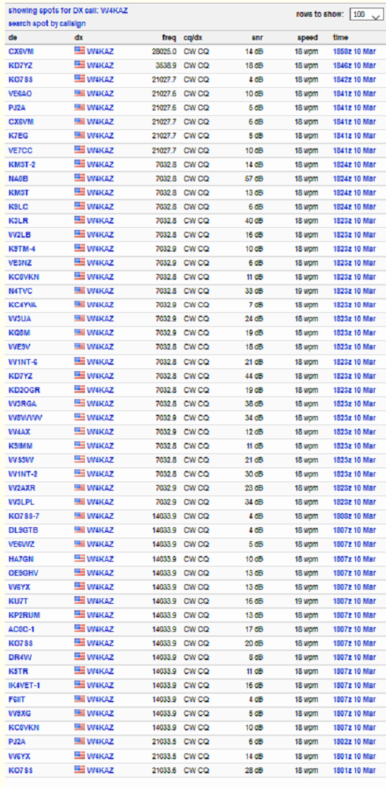
RBN Spots from 40m EFHW at 1800Z on 2021-03-11
The RBN spots from 1800Z show decent results, not too dissimilar from what I am accustomed to seeing from the permanent wire dipole antennas. The test antenna is deployed in a much-less-than-ideal location. The test EFHW horizontal section is running parallel to the horizontal tail of my permanent 160m inverted L, and it is only about 20 feet away. So I’m not too concerned with the locations of spotting stations. I expect to try a POTA activation soon, which will maybe be more interesting.
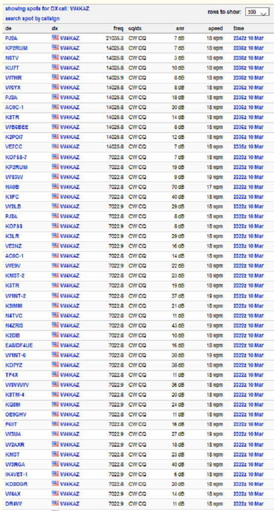
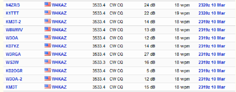
RBN Spots from 40m EFHW at 2345Z on 2021-03-11Â
Likewise the above set of RBN tests run later, near to and just after local sunset @2330Z, show fairly typical results.Â
RBN Spots from 40m EFHW at 2345Z on 2021-03-11Â Â *
I expected 80m results to be poor but they were maybe better than my low expectations. Nothing great, but certainly good enough for an easy to deploy portable antenna. Better to have some 80m capability than zero capability.Â
Next Question:Â What happens if I use a different transformer?