By w4kaz, created on 2019.11.09 at 15:43:10 | last changed on 2021.05.06 at 22:39:49 |
Many thanks to Guy, K2AV for tips, suggestions, and testing assistance to help resolve the following problems.
An unanticipated problem with fixing broken antenna systems is that it begins to work better. Well – “duh”, right?Â
After making repairs to the antenna switch and the 160m inv-L over the past couple of months, the antenna systems are nearing the end of a minor overhaul. Since about May, the CW Skimmer has been using a K9AY as the main RX antenna. For the period of 2 years prior it has been using the 160m Inv L as the RX antenna, until problems cropped up in May 2019[a broken connection on the feedline at the switch box.]
After correcting the broken connection and re-assembling the skimmer station, K2AV reported having spurs on harmonics when testing on 160m. Upon a closer I found several other stations for which the SDR was also generating harmonic spurs on higher bands for signals of 40-43 DB SNR into the skimmer station SDR.  This was resulting in bad spots to the RBN, and as is sometimes noted “results may be unpredictable”.
All of the spurs appear to be caused by overload mixing from nearby BCB stations on 680, 850, 1360, and 1510. Some of the problem was previously handled with the BCB filter constructed with notches tuned for 680 and 850. Upon re-assemble, the BCB QRM was still sneaking in.
The bulk of the issue has been resolved by bonding the BCB filter enclosure directly to the SDR enclosure. In a belt and suspenders approach, I constructed a second filter that has a higher cut off frequency.  It appears to function as designed, notching 1360, 850, and 680. It adds about 20db attenuation at 1510, and rolls off at about 1650 while applying less than a db attenuation at 1800 to allow 160m into the system. This second filter was placed at the input to the skimmer station preamplifier in the hopes of reducing the interference further.
Currently the result appears promising, as the signal SNR numbers from the skimmer seem to have benefited from the dual filtering scheme. Perhaps the stations at 1360 and 1510 were causing more overload than I originally thought. While neither is as strong as 680 or 850 into this QTH, both are over S-9 on the base radio using the same antenna for RX.
So now the curiosity about BCB filtering has been tweaked, and experiments modeling and building alternate filter choices are continuing.
If you are seeing bad RBN spots originating from the W4KAZ skimmer, please email the info so I can attempt to remediate the problems.
By w4kaz, created on 2019.09.29 at 16:44:08 | last changed on 2019.10.18 at 16:56:45 |
NanoVNA
Recently this NanoVNA product popped up on my radar, and like normal, I was a bit behind the group in discovering it. It is relatively newly available, but seems to be rapidly becoming known because it is both inexpensive and very functional. What a wonderful and useful project. There is a group devoted to the project. There is also a secondary product fork recently begun. The second fork will have a larger screen. Software will not be compatible between the two. (update….maybe more than one fork, rapidly changing).
The NanoVNA itself appears to well suited to the home hobbiest, both in price and utility. As an open source hardware design, being produced by various vendors, it is not coming out yet as a mil-spec “ruggedized” product. It is also not $50,000 USD. Also, caveat emptor. The calibration dummy load supplied with the units I obtained measured an intermittent 50K ohms instead of 50 ohms. A second unit supplied a load that measured 43ohms. [I used a known 50 ohm load for the calibrations.]
Dummy loads aside, it appears I wound up with a cheap copy of the cheap copy of the open source hardware. Yet both units appear to function, at least well enough for the 30Mhz of spectrum of interest here at W4KAZ. All images below were captured on a Samsung Galaxy S7, rather than spend a lot of time dorking around with rapidly developing beta software. Truth is – I was in too much a hurry to tinker to take the time for the software, which seems to be FB. Good enough is often “best”. Engineer the Possible. Plenty of time for software later.
Filters Tested
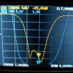
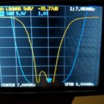
RTL-SDR: The RTL-SDR 2.6Mhz high pass broadcast band filter.  This filter is quite good. Its only drawback is that the cut off is above the 160m band. This helped a lot in testing to find RFI problems, but I needed a filter that allowed 160m. If 160m is not required this is an inexpensive rx only solution.  AE5X also has posted a quickie scan of this filter recently. My own scans…
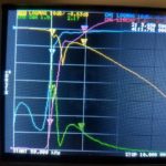
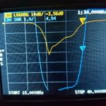
RTL-SDR BCB filter, at 3.93Mhz. SWR=2:1, RL=8.63db, IL= 1.4db
RTL-SDR BCB filter, at 3.93Mhz. SWR=2:1, RL=8.63db, IL= 1.4db
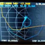
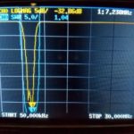
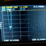
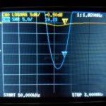
RTL-SDR BCB filter, at 1.81Mhz. SWR=16.3:1, RL=1.06db, IL= 50.5db
W4KAZ Broadcast Band Filter: While tracking down what I thought were RFI issues on the Red Pitaya CW skimmer, I obtained the RTL BCB filter above. Because its cutoff is at 2.6Mhz I needed something with a lower cutoff frequency.  As a home brew experimental project I came up with a BCB filter, designed using the AADE filter design program, available from KE5FX.   Â
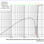
The BCB filter design is shown below, along with the projected rejection. This design is intended to have the cutoff as near to 1 to 1.2Mhz as possible. 680Khz and 850Khz stations are respectively 1.5 and 4 miles from this QTH, and the nearest 680Khz is a 50Kw station. The intent of the design was to null 680 and 850 as much as possible.  This filter also shows a DC short via the 100uh inductor. It can be removed if 60hz mains noise is not an issue.
After construction the filter was originally function tested by checking S-meter levels from the AM band up through HF and a few spectrum glimpses using the Red Pitaya with SDR programs. Using the NanoVNA is a lot quicker. In lieu of computer software for trace captures I just used a field expedient solution – snapping a photo of the teeny NanoVNA screen with my phone.Â
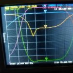
It is nice to see the real world corresponds to theory. The filter shows a 3db shoulder close to design at 1300Mhz. There is a 2:1 SWR shelf across the 160m band. Beyond 2Mhz it rapidly improves. Quite good for my purposes. Also surprisingly good for hand wound coils and ordinary NP0 ceramic caps thrown together without much[i.e., none!] testing of component values. I am not certain if I want to chance tinkering with the tuning of the 680 and 850 notches. Both notches came out about 100 KC lower than designed(not yet shown).
W4KAZ version of BCB filter. Built using NP0/C0G leaded capacitors, t-80-2 torroids, and a 220uh choke.
AADE predicted performance plot of the w4kaz BCB filter from DC to 10Mc. Note the nulls on 680 and 850.
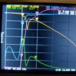
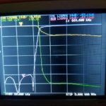
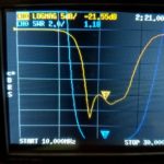
BCB SWR, insertion, and return loss from 50Khz to 3Mhz
W4KAZ homebrew BCB Filter 50kc to 30M SWR scan
Band Pass Filters:Â
The following set of band pass filters are all constructed based on the K4VX article “Band Pass Filters For HF Transceivers” . A good project, but these were originally only swept for SWR and not a lot of effort to properly tune them previously. NanoVNA to the rescue.Â
10m Bandpass Filter Â
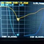
As originally built, 3:1 SWR range is from about 24Mhz to32Mhz. Minimum is at 25.7Mhz, and its usable on the lower end of 10m.
10m Bandpass filter scan from 15 to 40Mhz.
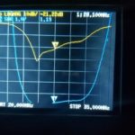
10m Bandpass filter scan from 20Mhz to 35Mhz.
10m Bandpass filter scan from 20Mhz to 35Mhz.
after NanoVNA tuning, a slight improvement across 10m:
Tuned 10m band pass filter scanned from 15mhz to 40mhz
Tuned 10m band pass filter scanned from 20mhz to 35mhz, Minimum at 25.400 Mhz
Tuned 10m band pass filter scanned from 20mhz to 35mhz, on 10m band
15m Bandpass Filter
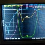
Bandpass filter scan for 15M filter
20m Bandpass Filter
Bandpass filter scan for 20M filter originaly tuned with MFJ analyzer by SWR
Bandpass filter scan for 20M filter after tuning with NanoVNA
40m Bandpass Filter
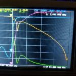
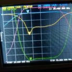
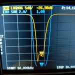
Able to tweak the 40m filter from -29.4db to -35.7 db, and filter covers 40m band easily.
Bandpass filter scan for 40M filter before re-tuning using NanoVNA
Bandpass filter scan for 40M filter after re-tuning using NanoVNA for a 6-7db return loss improvement
80m Bandpass Filter
????where’d it go?!?!?!?! This one was misplaced somehow……????
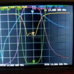
160m Bandpass Filter
Very bad news on 160m filter. Looks like a new repair project – not even close to “good enough”!
By w4kaz, created on 2019.06.08 at 12:27:11 | last changed on 2021.05.06 at 21:06:51 |
I have been using a telescoping fiberglass mast of one sort or another since 2005 or so. Most folks seem to be using these masts mostly as designed, i.e. relying on the friction fit, or using tape or hose clamps to keep the mast extended under load. None of those seemed ideal for my plans to use them with dipoles(inverted V config).
The first pole I obtained was from Henry, K4TMC (tmastco.com).(FWIW, I am acquainted with Henry via our membership in PVRC. Henry also sold me a very nice Elecraft K2 when he upgraded to the K3, and other assorted sections of surplus mast.)
This is the 32 foot pole, which results in about 29-30 foot of usable length once extended. Relying on friction fit, I ran into a couple of problems I think common to ALL of these similar type masts. The first problem is the amount of friction required to keep the poles from collapsing was also enough to make them difficult to collapse in very hot or very cold weather.(38C/98F or 0C/32F) Tape and hose clamps are usually enough to resolve that, but bring their own issues.
Tape tends to leave a lot of residue at the joint at 38C(i.e., ‘sticky mess’), which is a problem on sandy beaches. Sand does not enhance the experience of using one of these masts when it sticks to the joints. I also did not like the amount of pressure hose clamps required, nor the amount of time needed to install them in correct order(at 98F oceanside), or to fasten them without crushing the fiberglass accidentally. Because of “spontaneous collapsing” under certain types of pressure, the friction fit is not ideal for use with dipoles, my preferred antenna for portable ops.
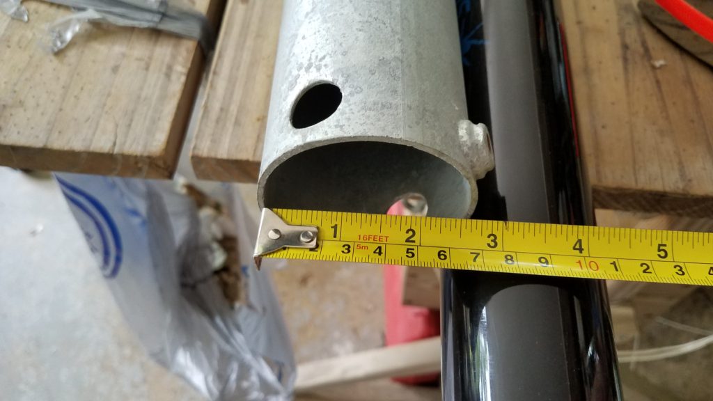
The solution I chose was to drill the mast and use 1/8 or 3/32 cotter pins at the bottom of sections just above where they rest when extended. The pin rests on top of the next lower section, so no problems trying to align holes through two sections. Saving another 1000 words……
A section of mast extended showing position of pin, which goes through only the base of the single section.
Over the past 10 years or so I have acquired a few additional masts. Primarily to have the ability to deploy more than a single antenna, but also as redundant or spare masts. [Two is one, one is none.] These additional masts include the 12m Spiderbeam pole, both a 28 and 32 foot mast from Jackite, a 22 foot mast that was marketed as a flagpole, and several Shakespeare 20 foot Wonderpoles. The Wonderpoles are used mostly to elevate the ends of the dipole legs when it seems appropriate(mostly constricted spaces).
The mast from K4TMC has seen the most use over the last decade. It has a good combination of stiffness and flexibility for its length. I had my doubts about drilling holes for the cotter pins, but the mast has been deployed for extended periods with little signs of anything more than minor cosmetic damage. The Spiderbeam mast seems to be much more flexible, which tends to negate is useful length as a center support for dipoles. Both Jackite masts seem to be the most rigid of the group, but I have used these less than any of the others – they are relatively new buys.
The disappointment of the group for me is the Spiderbeam mast. Its flexibility requires guying to keep it from noodling with the weight of a very light weight 40m dipole made of 18ga wire. Best practice seems to be best to attach the feedline to the mast for any of these type masts, but absolutely essential with the Spiderbeam. My Spiderbeam pole also becomes difficult to extend to its full length the more it bends, although that does help keep it from spontaneous collapse. Also more difficult to deploy in heavy wind at the beach due to flexibility, common to all but more pronounced on the Spiderbeam. The other masts are more self supporting when used with the auger bases. This may indeed have more to do with their overall shorter length, and the spiderbeam masts are indeed intended to be guyed by the manufacturer. I would prefer not to use guys to save time, but in several excursions I was unable to use the full length of the Spiderbeam mast sans guy lines. Even with guys the Spiderbeam pole had excessive droop in high winds oceanside, so the additional time required did not seem worth the effort. Taken all together the Spiderbeam mast was not taking my dipole significantly higher than shorter masts.
Auger Bases? Why didn’t I think of that? : The other divergence from the norm is my use of these auger bases. These auger bases are items I have scrounged from different sources. The first pair of them I obtained from Harbor Freight in the early 2000’s, where they were being marketed as beach umbrella stands. That source disappeared soon after my purchase. A second group of smaller augers[NOT pictured below] are marketed as “Aussie Augers”, but needed modification to use with the fiberglass masts(unless you don’t mind removing the end caps from the bottom).
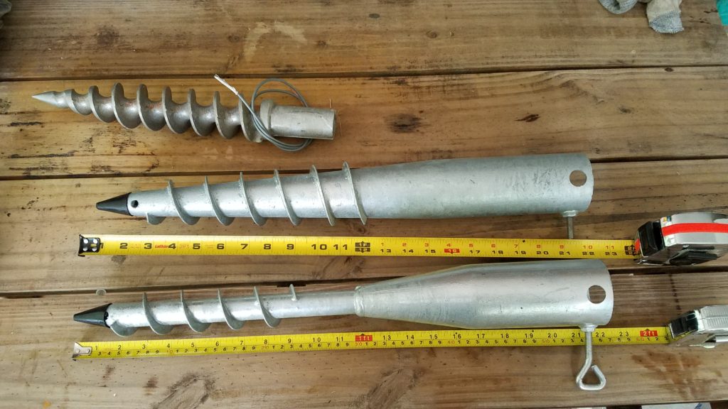
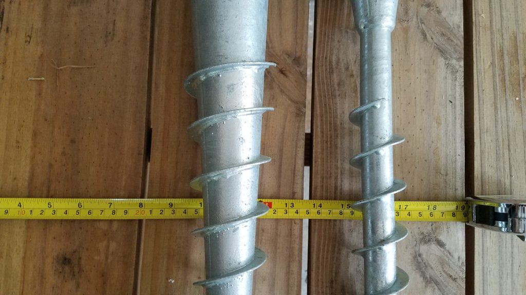
These augers pictured below were available via Amazon in the US in 2019. They work extremely well in sand. They are heavier gauge material than the Harbor Freight versions. The larger tapered base is my first choice for sand and seems to be the strongest. It would also work anywhere with a deep layer of loam or sandy topsoil. The base with the narrow welded on auger is more useful where the soil is less friendly, with stone or tree roots. I use the narrow base in my home yard, which is chock full of quartz stones and tree roots. It sometimes requires multiple placement attempts, but seldom takes more than a few minutes to install. For areas with no topsoil, shallow stone, or mountains, this solution might be less than ideal. The other caveat is leaving a hole in the deployment area.
Both bases are about 60cm in length(22 inches) and have a 60-61mm throat width(approx 2-3/8 inches). This is just barely wide enough for the Spiderbeam mast to fit without removing the base cap. All of the other masts are a bit smaller at the base and fit in easily. The large base has a depth about 178mm(7 inches) and the larger a depth of 127mm(5 inches). FWIW, with the smaller diameter masts I often insert a section of 2″ PVC into the base as a bushing sleeve, and the mast into the PVC bushing section. Large tapered base at Amazon [American Ground Screw Model 2] Narrow welded base at Amazon [American Ground Screw Model 1 with Cap ]
Two different types of auger bases for use with telescoping masts by W4KAZ
Two different types of auger bases primary difference is size. The auger on the left has threads down a tapered shaft. On the right, the auger shaft is a uniform width of tube welded onto the top section. The usable depth on the left auger is also about 2 inches more than the one of the right.
I don’t expect I have been the first to go down this less traveled path but have not seen it documented elsewhere. So some photos above for reference. I drilled 9/64 holes in the bottom of each nested section, just ABOVE the joints, and use 1/8 cotter pins.
My 10+ year old mast from K4TMC has been deployed numerous times. There is still only minor wear to the drilled holes, and zero cracking or vertical splits. YMMV. Caveat Emptor. An additional tip would be to have spare pins, and pins in at least two lengths. The bits of wire are used to keep the pins from vibrating loose in the ocean breeze. The also are used with coax to keep the feedline close to the mast. Generally I tape the feedline when using twinlead.
The choice of feedline is made on deployment depending on the distance from the antenna to the operating position. I use LMR240/RFC240 for the feedline drops when the operating position is close to the antenna, and 300 ohm ladderline from DX engineering for long runs.
N6TV useful links to all the required software files and extras, with proper credit to all the developers and enthusiasts who made it possible for simple folks like us to replace our failed QS1Rs with a Red Pitaya or two:
The oscillator itself is pretty simple, and is the bare essential hardware required for re-programming the oscillator for a needed single frequency to use with a Softrock Lite II rx.  It is based on what I saw in the the schematic of the Softrock Ensemble RX, nothing original, just pared down and hijacked from the original Ensemble design.  The Si570 part itself is the bulk of the expense of the oscillator, and the cost of the Si570 chip is almost as much as the Softrock Lite kit itself.   The oscillator signal is fed into the divider through a 10K voltage divider as in the Softrock RX.
So why an Si570 Programmable Oscillator ?
The RX Ensemble kit is a viable alternative expense wise.  It really depends on the intended usage.  Using separate Softrock Lites as single band CW skimmers leads to the choice of a programmable oscillator for customizing the center frequencies, especially for the high bands.  The method used for 20m using the third harmonic seems to result in a decrease in dynamic range.  That results in an increase in false mirror images being reported to RBN by the CW skimmer as actual spots.
Using the Si570, the oscillators can be set at the frequencies needed by the Softrocks, i.e. 4 times the center frequency.  (for 96Khz bandwidth the oscillator would need to be: 20m=56.188, 15m=84.188, and 10m=112.16).  A programmable oscillator also allows switching from 96Khz to 192 Khz bandwidth(20m=56.38,15m=84.38, and 10m=112.38).  Keeping just the bottom half of a 192Khz bandwidth CW skimmer would at a minimum eliminate at least 50% of bad mirror image spots.  There are also likely to be fewer stations CQ’ing below the “.096” section of a band(e.g., most often there is not so much regular CWactivity above 28.096 as there is below).  That is the idea anyway.
The Si570 Programmable Oscillator Prototype:
The first version is deadbugged on a bit of board scrounged from the parts bin. Â Not many parts, but a bit more PCBÂ real estate would have been better. Â Functional rather than esthetic. Â The USB connection is via the usb cable end clipped from an old computer mouse in the parts bin(unlabeled black coil in left of photo). Â Â “Engineer the possible”.
Si570 Programmable Oscillator board for 10m Softrock CW skimmer
Testing the original prototype board pictured resulted in three build mistakes to debug:  a missing 5v connection to the ATTiny and the reversal in polarity on both zener diodes across the USB data pins.  These mistakes prevented function without damage to the components.  After correction of the build errors the software was able to function with the Si570 as needed for both programming the oscillator(‘startup’) frequency and running as a stand-alone oscillator.
The Si570 when programmed for 112.36Mc was found to have an actual oscillation at close to 28.090 exactly from the Softrock divider, as measured with TS-590 and Elecraft K2.  This was with the oscillator inserted in-circuit as the Softrock Lite oscillator via a transformer(5 bifilar turns on a type 43 torroid core) and a 2.2k resistor.  The frequency is very consistent and stable when the power is cycled on/off.
Easy measurement of the actual frequency in place is good enough for initial setting up of the skimmer software. A few KC either way will make little difference in a CW skimmer set-up, as final adjustments were done in CW skimmer software to put the skimmer signals ‘on frequency’.  In this case the CW skimmer center frequency is nearly identical to the Si570 programmed frequency.  That has not been the case with the versions using ordinary crystal oscillators, those having a bit more drift off their nominal value.
A new Softrock Lite II is the 10m test bed, with 15m revision to follow. Â These two bands suffer the most from poor dynamic range and false mirror images. Â The 15m oscillator also has a nasty tendency to drift with temperature changes. Â If the modified softrocks perform as desired it will be time to pair these two bands with the best of the sound cards available. Â That will be a separate game of trial and error. Â The 20m softrock skimmer may also be retrofit, as using the third harmonic for the softrock center frequencies seems to adversely impact the dynamic range.
Photo of 10m Skimmer at W4KAZ
As an aside, the first 10m center frequency chosen was 28.060 into a 192Kc bandwidth sound card. Horrible choice, as it was close enough to the 15m harmonic that interference spikes were present on both bands every 900hz. Â Resetting the Si570 oscillator to place the center Fo for 10m at 28.080 greatly reduced(but not eliminate) the problem. Â Currently set on 28.090 as of 20150414. Â More tinkering required, and migrating the 15m Softrock over to an Si570 oscillator may help.
The current Skimmer package for 20m, 15m and 10m. 20m and 15m will likely be re-worked to use Si570 Programmable Oscillator.
Si570 Programmable Oscillator UPDATE, 2016-11-08
The Si570 oscillator as described was perfectly usable in this application. Â However 10m and 15m performance was was poor on the softrocks, the primary difficulty being a low dynamic range. Â This is indicated by mirror images that appear when SNR values on the actual signals were higher than 35dbSNR.
The most useful work around for this problem is to scan at 192Khz sample rate, and only use the lower half of the sample for the CW skimmer. Â Using the upper 96kc might be easier, as the center frequency could be set at 28.0Mc and 21.0Mc. Â The latter may ulimately be the best approach. Â There are unlikely to be any useful signals below the bottom of the bands, and those could be readily discarded as false or otherwise unusable(i.e., out of band).
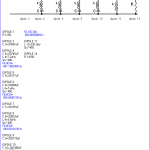
LINK LIST, Si570 Programmable Oscillator :
W4KAZ Schematic
Schematic for W4KAZ version of Si570 Programmable Oscillator
W4KAZ BareBones Parts List (PDF) (HTML with links)
By w4kaz, created on 2012.09.06 at 11:57:20 | last changed on 2021.05.06 at 21:07:45 |
Yesterday, having not yet thought of a better way to do a meaningful real-world test on the sound card with what is available in the KazShack, I fired up the 80m softrock on the ASUS Xonar DX for a bit of putzing around.
Test condx:
Transmitting a cw signal(a string of dashes at about 18wpm) at 5w into a dummy load on separate radio, noting the SNR readings obtained by CW skimmer from the SoftRock center frequency(353395x) to its upper limit. With the xonar DX set to 192khz scan rate, the actual upper limit on the readings was 3629.60. SoftRock connected to normal antenna system, a NE facing K9AY with W7IUV pre-amp. In summary, a sound card test using the SoftRock system as input source.
fq….—-SNR(dB) 3534.5—-42
3543-3593-42-40
3603——37 3613——35 3623——32 3629.6—-36
After CW skimmer collected a bit of data, the SNR readings above 3600 improved to 37-39.
So the worst case for CW skimmer(as currently configured) using a Xonar DX is being 6db less sensitive at the upper edge of the 192khz bandwidth than it is at the center. That is actually a lot better than I expected for an audio device pressed into service outside normal audio ranges (and I already liked the Xonar DX).
My curiosity is now nagging me to run the same tests on all of the other in-shack cards more methodically at their maximum scan rates(mostly 96khz), and to find a lower level outside signal source. I’ll try to recruit a fellow in the near field who will better be able to generate a low level test signal.
But with the WX here improving, all of that might not happen for several months. 😉
By w4kaz, created on 2012.08.24 at 17:07:02 | last changed on 2012.08.29 at 12:38:38 |
My testing sandbox server is running on an ancient Dell Optiplex 280 minitower, which has a P4 processor and 2gb of ram. Â Its been chugging along placidly on Ubuntu 10.04LTS. Â The 12.04LTS version has been popping up for a bit, and it seemed like it was being reported as a very solid release.
The install running in my VirtualBox partition went smoothly enough, but that was only a leap from 11.x to 12.04. Â Upgrading from 10.04 is a couple of levels to jump, so the possibility for problems increases.
So with some amount of trepidation I decided to run the upgrade process on the 10.04 sandbox. If the upgrade should barf completely, its not a tremendous loss.  If it works, the 12.04LTS version is supposed to be good through 2017(if I recall the upgrade notes correctly).
The upgrade seems to have been completely successful, with zero impact on the test bed. Â Sweeeeeet….. The 10.04LTS was mostly a plain vanilla install, but its nice that it made the leap with so little intervention.
This upgrade went far more easily than a prior upgrade(from 8.10 to 9.04). Â Very happy to see the Ubuntu developers have made the upgrade process so user friendly.
Very. Â Nice. Â Work.
So now the file server is good to go and can remain stable for the foreseeable future. Â Time to get back to hacking up some web apps for graphing the Reverse Beacon network data extracts.
Not so happy with the UNITY desktop, but at least it is easy to revert back to Gnome. Â Unity is kinda like the new Windows 8 – ButtHole Ugly. Â The very last thing I want is an interface that looks like a tablet. Â Bleh.
Never have understood why OS developers seem to think that 30 years of accumulated OS familiarity is so readily cast aside for their own vision of ease-of-use. Â Too little customer contact…. Â Most customers want their interfaces to function the same way they functioned yesterday(providing they actually worked yesterday), and changed only if they were broken. Â AKA, “New Coke Syndrome”.
By w4kaz, created on 2012.07.06 at 10:42:06 | last changed on 2021.05.06 at 21:08:01 |
Created a page of links and several related pages of information on the ongoing construction of the CW Skimmer station at W4KAZ.
Because of the nature of the blog package used for this website, it is easier to save this skimmer related info on ‘pages’ rather than as a “post” because it seems like a project that I’d like to have semi-permanently documented, and have the documentation easily found. Whooop…there it iz….Incomplete, but slowly growing, and probably to be frequently edited in the short term.
So in hindsight – I’m glad contest sponsors read my blog. 😉
Since the rule-parsing panned out to my immense satisfaction, it is easier to concentrate on the toy itself. Since then, skimmer stations sprouted, and the Reverse Beacon Network was born. That is a really interesting project. Its a great tool for checking propagation, comparing station signals, and getting impartial signal reports. Outstanding resource.
Unfortunately there is not a local skimmer station that is feeding the RBN. Spots from MD are not always useful in Central NC.
So it with the moon in phase and the planets approaching the grand alignment, it seemed like time to look into the subject of skimming.
Options
The Skimmer software comes with a component that is designed to work with the QS1R SDR. That combination is likely the ideal solution. So all I need is a fast Pentium i7 Quad core, and a thousand samolies…… Great idea, just not possible.
It has been done before…AC0C has documented the challenges and his solutions. Despite the validity of his conclusions, it is now possible to cobble together a scaled down version using scrounged computer hardware. Using softrocks, it is now very practical to put together a skimmer package for 160/80/40/20 meter bands with obsolescent computer hardware.  The price/performance ratio of the softrock is a huge factor. If they were a mass production commodity, they would probably cost under $10.
15m and 10m may be more of a challenge, so that has been shelved for the moment. So the softrock solution is not perfect. But there are solutions to that too. Future project….
The current project direction
So the game plan is to skim on 160m thru 20m using softrocks. 40m and 80m softrocks are done. Its not going to be as professional a finished product as AC0C’s, but it should function. Reclaimed from the off-lease refuse stream are an Dell Optiplex 745sff and a Dell optiplex 360 SDT. Both of these boxes require low-form-factor cards. The on-board sound of the 745 leaves something to be desired, but the 360 has an on-board sound card capable of 192khz bandwidth. So small form factor add-in cards are needed to run skimmer on multiple bands. Four bands on two computers.
Other Naughty Tidbits….
The Asus Xonar DG is a small form factor sound card that turned out to be a fabulous bargain. It allows only 96khz bandwidth, but has excellent dynamic range for its cost. Sounds great with music too. Also had an Asus Xonar DX, which is higher fidelity than the Xonar Dg, and offers 192khz bandwidth with a softrock. The sound card issue is the real sticking point in this design, but the Xonar cards are able to coexist with the onboard SoundMax devices in the Dell boxes.
Not so much luck with a Soundblaster Live 24. Experiments installing and using the Soundblaster were problematic. Compatibility issues with the other sound devices and SDR software crashes. The Asus cards are much higher quality, but attempts to pair either with the soundblaster caused problems. Attempts to install both Xonar cards in the same system were also buggy. So the Soundblaster is sidelined for later rainy day experimentation, the ASUS cards are each on a different host system, and it is fortunate that the onboard sound cards are useable.
The final compromise chosen was to install the 192khz Xonar DX in the Optiplex 745 that has 48khz onboard SoundMax. The Xonar DG is installed in the Optiplex 360 that has 192khz SoundMax onboard sound. In testing the Xonar cards work very well with all of the SDR software tested. The SoundMax cards are noticeably less capable, but not terrible.
Mix and Match
The skimmer sessions sound card pairings in daily usage are likely to be:
Those pairings should spread the CPU load somewhat. A live test on 40m and 80m during CQ WPX should give me a benchmark for CPU loading. CW Skimmer allows the definition of the maximum number of active decoders, and I expect to get some insight on setting those values to help moderate the load. Currently, allowing 500-600 decoders seems workable.
During 160m contests, the 160m skimmer will likely switch to a wider bandwidth card, at least 96Khz. The fall contest season will allow more testing to determine if the 192khz skimmers will need to be narrowed during contests or throttled by limiting the max number of decoders – maybe both. Also, the nature of any given contest may also make temporary changes to the line-up appropriate. But that’s the basic setup.