[edited for links and notes, 2023/07/15] The original trap dipoles were constructed using coils and caps. Using Rg-58 for the coax style trap dipoles was rejected because of the weight and size of rg-58 coax traps. Using RG-58 defeated the primary goal of making the antenna as light weight as possible.
Somewhere I picked up the notion of using rg-174 or rg-316 type mini coax to make the traps. It looks like the voltage ratings on the rg-174 is higher(1100v rms), so that was chosen for the first experiments. If luck holds out, the tiny coax will be sufficient for use on the dipole traps for a full 100w CW. Using the smaller lighter mini coax will allow for lightweight construction from easily available materials that can be easily supported using telescoping fiberglass masts like those available from Spiderbeam, MFJ, or Jackite. i.e., perfect for portable, field day, rover QSO parties, or POTA/SOTA.
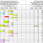
The trap calculator program hosted by KC1KCCgave me some starting numbers to work with, and actual trap measurements came out quite close to the calculated values. [alternate calculator at K7MEM]  The traps are built with the coax coils wound reasonably tight to the form, and the coils were taped down with electrical tape prior to taking measurements. These are all wound on small sections of the same sort of plumbing drain tailpieces that are 1.5″ od (38mm od). (e.g., in the US available from Lowes or any hardware store selling plumbing supplies.) The table below are of traps as built and tested with the nanovna.
frequency
turns rg-174
27.7
3.33
20.66
4.33
13.75
6.1
6.75
10.3 [calculated]
Update, 2024-04-04
Received a new 1 inch o.d.(~25mm) form material that is lighter. testing.
Freq———–# turns calculated——#turns actual——- 27.7Mhz—>5 turns (approx)—–> 5 turns, 24.8Mhz(use 4.5?)
20.66Mhz–> 6.25 turns————> 6.25 turns, 19.65Mhz(use 6)
13.75Mhz—> 8.75 turns ——–> 9 turns, 13.5Mhz & 13.7Mhz
6.75Mhz—-> 16.33 turns END 2024-04-04 Update
Test Antennas:
The test antennas were built for the CW segments of each band. With the best SWR centered on the xx.070 area it will probably give enough coverage for both CW and SSB operation without a tuner. An 80m/40m version will require tails for 80m adjustments.
Testing of two antennas was done before the May 2022 CQ WPX CW contest. The 20m/15m version tuned easily….after I figured out I was working on that instead of the 10m antenna. Read those labels, because at least I had them labeled properly when they were built several weeks earlier. The 10m/15m version also tuned easily.
[aside: the 15m/20m trap is now in service as the skimmer station antenna, after a recent storm broke the 160m inv-l]
Although I missed the WPX contest, I soon got a chance to do antenna testing at 100w levels.  Both antennas handled the power easily with no signs of SWR rise. Both were tested at 10 seconds, 30 seconds, 60 seconds and five minutes of CW key-down.
Hoping for good conditions in FD to allow testing of the 10m/15m version. Sunspots, do your thing!
[2023-07-15 additional notes] The coax traps began showing swr problems on 10m after a few months in the weather. Expecting this to be a problem with water intrusion. testing the use of WeldBond glue as a sealant. [alternative….Elmers ProBond] Also testing the adhesive as a sort of q-dope to seal the coils on the form.
By w4kaz, created on 2021.03.08 at 15:53:33 | last changed on 2021.03.12 at 22:12:18 |
Just about the only wire antenna in common use I had not experimented with is the End Fed Half Wave(EFHW). So WTF. May as well give it a go.Â
2021 planning had me booking a stay on Cape Lookout National Seashore(CALO) for the end of June rather than the end of July. I tried unsuccessfully to make the reservation in 2020, but could not. Success for 2021. So my FD 2021 will be from Cape Lookout.Â
Given the layout of the cabin I prefer at CALO campground I decided to tinker with the EFHW as a possible solution for allowing multi bands with least effort. The “least effort” factor is growing more important with each passing year. But the EFHW itself piqued my curiosity as well, and it seems it my provide a solution to the “least effort” vs. “works well” conundrum.  Â
So, here lies the experimental portion.  NUMEROUS versions of the classic 49:1 transformer are documented on WWW and in the now ubiquitous scrootoobe video. Version guidelines exist for either 80m or 40m multi band versions. Quite typically I chucked some of that and decided to re-invent the wheel – because what is the fun of experimenting if you are just going to follow the cookbook? Wellll…..not quite that either.
Where to start
Looking for a 40m size and decided to try modeling out a 40m EFHW fit out with a loading coil and tag end to allow 80m or 75m. The idea is to have an antenna that the floppy fiberglass masts would be able to support easily in the normal 20 knot winds typical on CALO. The feed point will be at about 4 feet high as I expect to deploy it. The mast will support the wire vertically to about 30 or 35 feet, depending on which mast is used(Spiderpole or Jackite or K4TMC). The rest of the wire will be stretched out horizontally with the coil supported by a second mast.
This deployment will have 80m or 40m basically functioning as half wave in an L configuration. 20m will probably have a larger horizontal component than the vertical section, and if it works there 15m/10m will provide who-knows-what. i.e., “PERFECT!” – for values of “perfect” where whatever happens is perfect.
Modeling showed best result with the wire between the feed and the load at a longer length than I expected at 70+ feet.  Using insulated wire for actual construction, I expect that to be shorter in real life.  I plan to test with a .05wave counterpoise, and use a 6 foot coax jumper at feedpoint. The real feedpoint will be a current choke at the end of the coax jumper. It seems likely the shield of the coax jumper will act as another counterpoise. Maybe another choke at the radio end.
Transformer Conundrums
The item I had more questions about was the step-up transformer. A lot of conventional wizzdom surrounding the 7:1 turns ratio versions. I chose to give myself more options and provide multiple taps, and use the larger ft-240-43 size toroid to allow 100w.  Hopefully this will give less core heating. Then two turns vs. three turns on the primary was considered. Initially I favored using three turns on the primary.  I expect 80m to be more useful than 10m going forward.  Physical reality – two turns seemed more practical with the 16ga wire I used.Â
The other wildcard I threw into the construction detail was about sticking to the “norms” of putting the taps on nice-and-easy turns ratios.    While waiting on my toroid order to arrive, I stumbled across N8NK’s videos. I found the playlist on EFHW and UNUN’s interesting viewing. The main idea I fortified was to tap the toroid in several different places. That would have been more versatile using 3:1 windings. Even with 2:1 windings I still liked the range of impedances available by placing “irregular” taps, i.e not on the even multiple windings. With 3:1 I had expected to place the taps on every 4th turn. With 2:1 windings I thought maybe every 3rd turn but with 6 taps every 2nd turn was “good enough”.
The only genuine benefit that conventional “even numbered taps” provides is ease in predicting the transformation factor(i.e., 7:1 turns gives 49:1 step up). To switch the flip I decided to tap the transformer at 4.5:1, 5.5:1, 6.5:1, 7.5:1, 8.5:1 and 10:1. (FWIW, that should be stepping 50 ohms up to about: 1013, 1513, 2113, 2813, 3613 or 5000 ohms.) Just for grins, it is easy to test with the ordinary antenna analyzers and a resistor test box(or well stocked junk box). Â
If it is important to your thought process, measure the damn unun to be sure. To simplify, the secondary is actually tapped on turn #9,#11,#13,#15,#17, and #20. With 2 primary turns and just 5 taps on secondary, tapping every 3 turns at #8, #11, #14, #17 and #20 should allow matching impedances of 750, 1513, 2450, 3616, or 5000 ohms. That includes the obligatory 7:1 ratio for purists. I only chose to use the odd taps as an appeasement to my increasingly contrarian curmudgeonly nature.
Precision Optional
 I figure to just use the antenna with the tap that provides the best SWR. I can then produce a cheat sheet for each band. I would like to have a best choice for each band. If it turns out the same tap works best for all bands – so much the better.  If they are NOT all the same tap I also want compromise choices that will allow one tap to allow operation on several bands without moving the tap. Another tradeoff option – sometimes moving the tap will be easy, sometimes inconvenient.
Functionally we can call it good if some doing RBN compares to permanent dipoles prove it to perform acceptably. The truth is I don’t care what the actual step up ratio might be. I just want the antenna to function, and experimentally finding a good tap is “good enough”. We are hoping that the taps provide enough options for multi-band operation with a good match. It will be nice if a single tap is good on all bands. It is not a deal breaker if changing bands requires moving a tap that can be reached at ground level.
Engineer the possible. Mind the trade-offs, because “best” can be the enemy of “good enough”.
By w4kaz, created on 2019.09.29 at 16:44:08 | last changed on 2019.10.18 at 16:56:45 |
NanoVNA
Recently this NanoVNA product popped up on my radar, and like normal, I was a bit behind the group in discovering it. It is relatively newly available, but seems to be rapidly becoming known because it is both inexpensive and very functional. What a wonderful and useful project. There is a group devoted to the project. There is also a secondary product fork recently begun. The second fork will have a larger screen. Software will not be compatible between the two. (update….maybe more than one fork, rapidly changing).
The NanoVNA itself appears to well suited to the home hobbiest, both in price and utility. As an open source hardware design, being produced by various vendors, it is not coming out yet as a mil-spec “ruggedized” product. It is also not $50,000 USD. Also, caveat emptor. The calibration dummy load supplied with the units I obtained measured an intermittent 50K ohms instead of 50 ohms. A second unit supplied a load that measured 43ohms. [I used a known 50 ohm load for the calibrations.]
Dummy loads aside, it appears I wound up with a cheap copy of the cheap copy of the open source hardware. Yet both units appear to function, at least well enough for the 30Mhz of spectrum of interest here at W4KAZ. All images below were captured on a Samsung Galaxy S7, rather than spend a lot of time dorking around with rapidly developing beta software. Truth is – I was in too much a hurry to tinker to take the time for the software, which seems to be FB. Good enough is often “best”. Engineer the Possible. Plenty of time for software later.
Filters Tested
RTL-SDR: The RTL-SDR 2.6Mhz high pass broadcast band filter.  This filter is quite good. Its only drawback is that the cut off is above the 160m band. This helped a lot in testing to find RFI problems, but I needed a filter that allowed 160m. If 160m is not required this is an inexpensive rx only solution.  AE5X also has posted a quickie scan of this filter recently. My own scans…
RTL-SDR BCB filter, at 3.93Mhz. SWR=2:1, RL=8.63db, IL= 1.4db
RTL-SDR BCB filter, at 3.93Mhz. SWR=2:1, RL=8.63db, IL= 1.4db
RTL-SDR BCB filter, at 1.81Mhz. SWR=16.3:1, RL=1.06db, IL= 50.5db
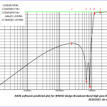
W4KAZ Broadcast Band Filter: While tracking down what I thought were RFI issues on the Red Pitaya CW skimmer, I obtained the RTL BCB filter above. Because its cutoff is at 2.6Mhz I needed something with a lower cutoff frequency.  As a home brew experimental project I came up with a BCB filter, designed using the AADE filter design program, available from KE5FX.   Â
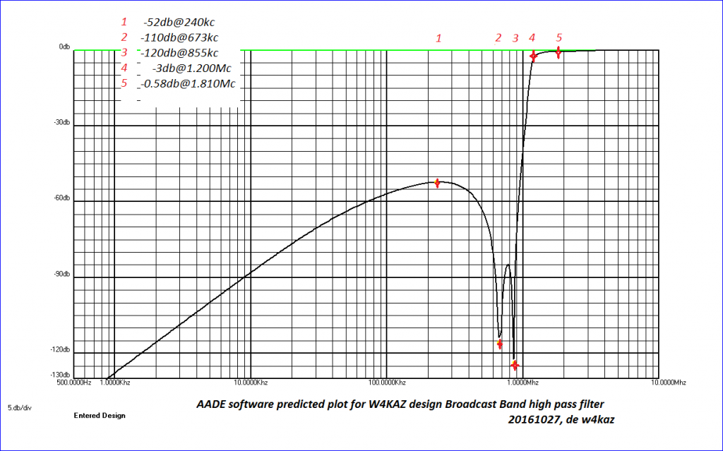
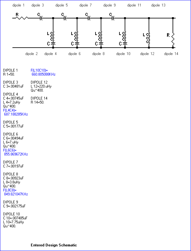
The BCB filter design is shown below, along with the projected rejection. This design is intended to have the cutoff as near to 1 to 1.2Mhz as possible. 680Khz and 850Khz stations are respectively 1.5 and 4 miles from this QTH, and the nearest 680Khz is a 50Kw station. The intent of the design was to null 680 and 850 as much as possible.  This filter also shows a DC short via the 100uh inductor. It can be removed if 60hz mains noise is not an issue.
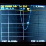
After construction the filter was originally function tested by checking S-meter levels from the AM band up through HF and a few spectrum glimpses using the Red Pitaya with SDR programs. Using the NanoVNA is a lot quicker. In lieu of computer software for trace captures I just used a field expedient solution – snapping a photo of the teeny NanoVNA screen with my phone.Â
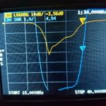
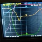
It is nice to see the real world corresponds to theory. The filter shows a 3db shoulder close to design at 1300Mhz. There is a 2:1 SWR shelf across the 160m band. Beyond 2Mhz it rapidly improves. Quite good for my purposes. Also surprisingly good for hand wound coils and ordinary NP0 ceramic caps thrown together without much[i.e., none!] testing of component values. I am not certain if I want to chance tinkering with the tuning of the 680 and 850 notches. Both notches came out about 100 KC lower than designed(not yet shown).
W4KAZ version of BCB filter. Built using NP0/C0G leaded capacitors, t-80-2 torroids, and a 220uh choke.
AADE predicted performance plot of the w4kaz BCB filter from DC to 10Mc. Note the nulls on 680 and 850.
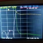
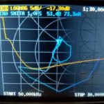
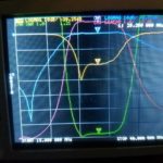
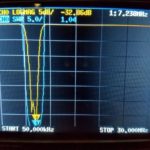
BCB SWR, insertion, and return loss from 50Khz to 3Mhz
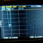
W4KAZ homebrew BCB Filter 50kc to 30M SWR scan
Band Pass Filters:Â
The following set of band pass filters are all constructed based on the K4VX article “Band Pass Filters For HF Transceivers” . A good project, but these were originally only swept for SWR and not a lot of effort to properly tune them previously. NanoVNA to the rescue.Â
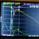
10m Bandpass Filter Â
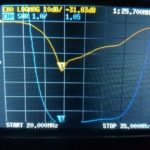
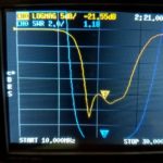
As originally built, 3:1 SWR range is from about 24Mhz to32Mhz. Minimum is at 25.7Mhz, and its usable on the lower end of 10m.
10m Bandpass filter scan from 15 to 40Mhz.
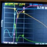
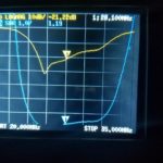
10m Bandpass filter scan from 20Mhz to 35Mhz.
10m Bandpass filter scan from 20Mhz to 35Mhz.
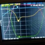
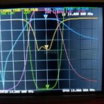
after NanoVNA tuning, a slight improvement across 10m:
Tuned 10m band pass filter scanned from 15mhz to 40mhz
Tuned 10m band pass filter scanned from 20mhz to 35mhz, Minimum at 25.400 Mhz
Tuned 10m band pass filter scanned from 20mhz to 35mhz, on 10m band
15m Bandpass Filter
Bandpass filter scan for 15M filter
20m Bandpass Filter
Bandpass filter scan for 20M filter originaly tuned with MFJ analyzer by SWR
Bandpass filter scan for 20M filter after tuning with NanoVNA
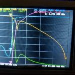
40m Bandpass Filter
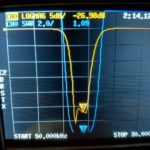
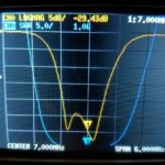
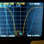
Able to tweak the 40m filter from -29.4db to -35.7 db, and filter covers 40m band easily.
Bandpass filter scan for 40M filter before re-tuning using NanoVNA
Bandpass filter scan for 40M filter after re-tuning using NanoVNA for a 6-7db return loss improvement
80m Bandpass Filter
????where’d it go?!?!?!?! This one was misplaced somehow……????
160m Bandpass Filter
Very bad news on 160m filter. Looks like a new repair project – not even close to “good enough”!
By w4kaz, created on 2019.09.15 at 15:29:37 | last changed on 2025.01.06 at 10:06:15 |
The Project and Situation: After quite a bit of trying over the past 15 years to find the best way to pull dipoles up into the closely packed trees in the yard it is clear the options are limited. Having the dipoles favor the NE/SW directions are the goal, but the arrangement of the best supports make this difficult. To beat this problem a combination of single band and multi band fan dipoles were used. [No, the “chainsaw solution” is not an option – yet.]
The primary supports are now occupied with supporting a 160m inverted L and another with a vee dipole for 80m. These are not high enough for direction to make much difference, but are in convenient locations. So everything else needs to fit around those two primary constraints.
The current problem is that there is really only one support that easily allows stretching out the legs of a 40m dipole in the desired directions while also achieving a good height for 40m(almost 50′). The other high supports will only allow the antenna to be deployed favoring a N/S direction(i.e., legs are stretched out E/W).
Using fan dipoles has come with its own practical problems. The dense tree branch coverage tends to tangle in the multiple wires of the legs. Then the fan legs have become entangled in heavy winds. So it is both a problem deploying the antennas, but also the SWR issues when legs are entangled after bad WX. An ongoing maintenance issue.
Alternate solution: trap dipoles. With dual band trap dipoles, it seems like it may be easier to arrange the antennas in favorable directions AND at good heights. The traps are relatively small compared to the mess of multiple wires on a fan, so also maybe it will be a bit easier to navigate dense branch cover of the biological deciduous antenna support structures. The downside is in the extra effort required in constructing the traps, tuning them to desired frequencies, and tuning the antenna legs for each desired band.
What’s the frequency, Kenneth?!? Using EzNEC 6 I ran models with trap data. Based on those results I initially decided to use traps tuned for just above the top frequencies of any given band(e.g., on 20m tuned for 14.400). I’m willing to live with the trap losses for the advantage of maintenance simplicity. Models showed tuning traps for the top end resulted in wire lengths that are the same as a single band dipole, or slightly longer. I then chose to build antennas with traps above the high end of the band based on the following.
A trap resonant frequency above the band results in the dipole wires being the same length or slightly longer than the single band dipole at the trap frequency
A trap resonant frequency below the band requires the dipole wires to be shorter than a dipole for that band. This might be worth pursuing if trying to reduce the antenna length.
there were already a few spare dipoles laying about, and if the traps project flopped they would still be usable mostly intact if traps designed above band,
I’ll probably be mostly using them on CW so maybe a tad less loss with trap rez at opposite end
the gut feeling that a 20m trap resonated at 13.900 would maybe have more loss than the trap at 14.4 when used at 14.025.
NOTE: SEE Part 2 for notes on how these initial assumptions changed!
Research: The traps will inevitably add unwanted weight to the antennas, and I wished to keep them as lightweight as possible. The reasoning for light weight was to extend the project to portable dipoles deployable on telescoping fiberglass masts. So I ruled out using one of the many coaxial trap designs simply to save weight where possible. For coil forms I chose to use small pieces of 1.5″ plumbing waste pipe cut from small sections of what is sold in the US as a “drain tail piece”. This is thin wall pipe, and much lighter than ordinary schedule 40 PVC. The second form material tried AND ABANDONED is 3.4 inch PVC sched 40.
Excluding the coax trap articles, there are relatively few trap dipole projects written up or documented in places accessible via internet searches. The best[most relevant] source is an ARRL antenna book article on a 2 band trap dipole. W8JI also has some interesting trap info published. Although it does not cover the specifics on the options I chose, it led me to the final result. My choices were made based on materials already on hand(wire, capacitors, and coil form material). Engineer the possible.
Initial Trap Construction: The available values of capacitors also drove the selection of trap resonant frequencies. On this point I made an effort to follow W8JI’s information and make the traps resonant off of the desired operating frequencies to minimize trap losses. Beyond this guideline I could locate nowhere any info to indicate if certain values of inductance vs capacitance were better or worse. A larger inductor will allow the antenna to be shorter overall, but the length of the dipole legs was not a restricting parameter for my project. This was merely about having the dipole resonant on 2 bands. Also, the capacitors are 2KV and 3KV 5% tolerance ceramics from Panasonic that I have used previously in band pass filter projects with great success. (NOTE: MORE ON THIS LATER!!!)
Coil Guidelines????: Guidelines for winding the coils are also a bit of guesswork, beyond W8JI’s testing results that show the highest losses occur on the resonant frequency of the trap. I simply started with the inductors, targeting a value of 6uh, initial turns counts generated by a random calculator found via internet search. Then trial and error on actual coil winding. Calculated inductances are based on trap resonant frequency measurements recorded and on the assumption the 5% caps were the most accurate component. Inductances are then calculated from cap face values and resonant frequency.
Test coils for the traps were close wound with #14 THHN stranded housing wire. They were close wound by hand as tightly as possible onto the forms. Coil Q is probably lower than it could be, but the close winding was a compromise accepted for ease of construction and ease of replication. Four inch lengths of 1.5″ waste pipe and three inch lengths of 3/4 inch PVC were tried. The latter were discarded as unsuitable.
Experimenting With the Coils and Caps: The 5% Panasonic caps on hand typically measure very close to the marked nominal values, much better than any 5% or 10% silver mica caps I have used in similar projects. I found that coils wound with similar technique and the same number of turns would reliably resonate within a range of +/-100 to 200hz. Generally the accuracy and reproducibility is better at 7 and 14 Mhz than at 28Mhz. The coils at the higher frequencies have fewer turns, and smaller differences in inductance and capacitance have a larger effect on resonance.
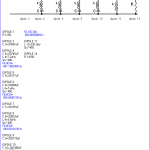
Initial coil test data
A group of several capacitor values were used along with an MFJ-259C as a grid dip meter to find the resonant frequencies. Pickup coupling coil was a coax jumper terminated on the business end with gator clips and a short length of #14 wire formed into an adjustable sized loop.
Some initial experimenting with the number of turns on the inductors was based on these available values of fixed capacitors. The first inductor was 12 turns on the 1.5″ forms, then resonance was tested with the values of capacitance that were on hand, or able to be easily derived using series and parallel pairs. It was then relatively simple to find the number of turns needed to be able to produce a trap resonant at a given frequency. I also wound coils on the same form material using 7 and 9 turns, and measured resonance for these.
By w4kaz, created on 2016.10.28 at 21:37:30 | last changed on 2021.10.24 at 13:37:45 |
Update 2021-10-24. Additional info on setup by Bjorn, SM7IUN.  Bjorn describes set up for running a second skimmer thread, but the forked Red Pitaya output can also be used to run a skimmer thread and an SDR with some experimentation. see: https://sm7iun.se/redpitaya/cwskimmer/
[Updated 2016-12-23, see text on Compatibility issue]
Recently discovered an interesting,  affordable,  and relatively new product called Red Pitaya, designed as an open source based piece of test equipment. As a piece of test equipment the Red Pitaya has basic oscilloscope, spectrum analyzer, and signal generator apps available. The apps are designed to run as web applications with Red Pitaya board running a custom Linux and acting as a web server.  Currently the apps are quite basic, but useful despite their simplicity.
With the SDR apps, Pavel has taken this little Red Pitaya board into the areas of interest to many ham ops. The SDR receiver app has the ability to function with several currently available SDR programs. The ability to support feeding six channels into CW skimmer server is of particular interest. There are also transceiver apps which are being used by experimenters to build Red Pitaya based transceivers.
Red Pitaya
The Red Pitaya itself is a board that runs a customized linux OS(their term is ‘ecosystem’) off of an SD memory card. The board has two RF inputs and two RF outputs for use as the heart of a test system. 5V USB power supply input requires 2A. The board has a heat sink on the CPU but a small fan helps cooling. It can connect via ethernet to the network or via a wireless connection. The OS and apps are downloaded from the Red Pitaya website.  SDR apps are available from both the Red Pitaya site and directly from Pavel Demin’s website.  This little SDR kludge is a viable substitute for the Softrock skimmer system previously being run @W4KAZ.
SDR Uses and v0.96 Compatibility Issue
A couple of issues turned out to be a mix of hardware and software problems. The largest problem was a software incompatibility issue between the [then]latest OS v0.96 and the SDR software. This caused problems in the SDR with interference that looks like intermod artifacts. Too much time was spent here looking for hardware problems before stumbling across the documentation on the issue. The solution was simple. It simply required building an SD card with the previous OS version v0.95, and  then configuring(secure password) then re-installing the SDR app.
A couple of the SDR apps available on Pavel’s site originally included an OS that did not allow a persistent password change. To avoid that security vulnerability, the original SD card here was built with v0.96 of the OS. As of October 2016, do NOT try to use v0.96 OS with the SDR apps. V0.95 works with the SDR. Better to have several SD cards with different OS versions should you need a more recent OS for new apps as they are developed.  [Update 2016-12-23.  Per comment from Pave Demin, the SDR applications have been updated and should now work with v0.96 and v0.97 of the Red Pitaya ecosystem.  Not yet migrated to the updates here in the W4KAZ SDR setup.]
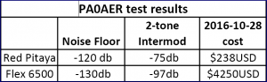
There is not a tremendous amount of information available, as folks are just beginning to explore the possibilities. PA0AER has an interesting post, with a few findings of his summarized in this table.
Yeah, -120db floor and 75 db of intermod suppression should work just fine in a CW skimmer application. Â
Keep in mind, the softrock system being replaced has about 45db of useful dynamic range as implemented here. Plus we get the bonus of using Red Pitaya as a minimal spectrum analyzer and oscilloscope. Maybe even a VNA app.
The time spent here going in circles chasing my non existent hardware issues was not a waste. The power supply was cleaned up with better filtering.  Very nice.  Using the AADE filter design program we also came up with a simple-to-build design for a high pass BCB filter.  This filter optimizes the nulls at 680am and 850am, and attenuation drops off rapidly above 1Mc the broadcast band.
This BCB filter exhibits low loss on 160m, with the modeled 3db cut off frequency being at about 1.2mhz.  Ordinary C0G/NP0 capacitors are used in its construction, having had acceptable results with that type with the W3LPL design receive only band pass filters.  The result was good with testing on the base station.  The difficult part was finding good leaded C0G/NP0 capacitors in proper values to use for construction. Through hole components are becoming rare.  NOTE: Be aware – As designed this filter is a short circuit at DC via the inductor at “dipole 12”.
AADE predicted performance plot of the w4kaz BCB filter from DC to 10Mc. Note the nulls on 680 and 850.
W4KAZ version of BCB filter. Built using NP0/C0G leaded capacitors, t-80-2 torroids, and a 220uh choke.
The plot projected by the AADE filter design program above is a best-case prediction. Â WPTF, 50kw at 680 and WPTK, 10kw at 850 have transmitters about 3 kilometers and 12 kilometers respectively. Â They produced all sorts of intermod in the softrock system. Â The BCB design here is tailored to place the largest nulls where they might do the most work in the KAZshack. Â Getting the 3db cutoff at 1.2Mc was just to try to keep the losses as low as possible on 160m. Â To get an idea of its performance, I plugged it into the station and took S-meter readings on the Kenwood TS-590s. Â The BCB filter dropped WPTF at 680 from pinning the S-meter down to just another strong S9+ signal, not even 10 over S9.
S meter comparisons on the TS-590s using the W4KAZ BCB filter and built in attenuator
Skimming with Red Pitaya SDR
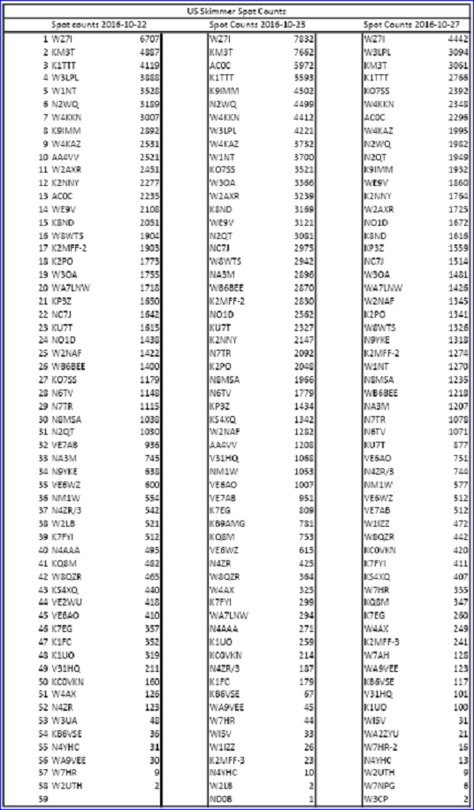
With the software issues corrected, let the CW skimming begin. Â Skimming tests seem to have spot signal levels from Red Pitaya SDR slightly better than those from the Softrock skimmer system. Â Full system stress test coming during 2016 SS CW. Â The Red Pitaya also seems to be very frequency stable, something that was a minor issue with the softrocks. Â When running PowerSDR, comparing Red Pitaya by ear shows it to be a bit less sensitive than the main station rig, a Kenwood ts-590s.
Does it work?
Random selected North American spot counts from days with W4KAZ skimmer station under Red Pitaya
System Reconstruction – Permanent New CW Skimmer
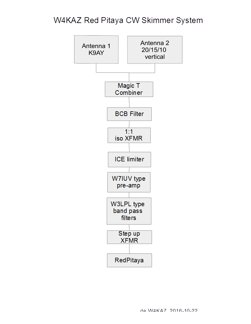
After a good shakedown voyage through Sweepstakes CW, it will be a good time to re-arrange the test Red Pitaya SDR system into a more permanent and compact single system. Â Â One of the dead softrock CPU’s will donate a nice clam shell computer case, and all of the components should fit easily. Â The plan is to wall mount the completed system near the shack cable entrance. Â The softrock system will be raided for its discrete components, the W3LPL style band pass filters as well as the W7IUV pre amps. Â New splitters will be built for the new system to allow for antenna options to change in the future.
Unexplored are some more experimenting to find a proper matching transformer and  Red Pitaya input jumper combinations for the best results.  Some research into the transceiver experimenter comments indicate using a step up transformer is best.  Some have also made mods to the front end that are supposed to boost the sensitivity by lowering the noise floor significantly, from 9 to 12 db.  Currently using a 3:1 cascaded into a 4:1 transformer as step up, with the input attenuation pads bypassed via jumpering on input#1.
Block diagram of likely W4KAZ Red Pitaya SDR CW skimmer system
Important Notation[see update]:
If you choose to experiment with Red Pitaya and the SDR apps,  be sure to create your bootable SD card from a compatible OS.  If you do not, you will be very disappointed at the 25db BDR and the interference and low performance you will experience.  Currently, as of 2016-10-28, the 0.96 ecosystem/OS IS NOT COMPATIBLE with the SDR apps from Pavel Demin.  Either use the ecosystems Pavel has or the last archived version 0.95 from Red Pitaya’s archive.  Do NOT TRY SDR with v0.96 OS!  Been there, done that, have a clean power supply and nice BCB filter to show for it.  [Update 2018-12-23.  Per comment from Pave Demin, the SDR applications have been updated and should now work with v0.96 and v0.97 of the Red Pitaya ecosystem. Migrated to the updates 2017-11-15 here in the W4KAZ SDR setup.]
The Red Pitaya ecosystems come with default root passwords. Suggest resetting your password ASAP.  Also, at least one of the pre-built ecosystems Pavel provides does not allow a persistent root password change.  I suggest using the 0.95 the current ecosystem from Red Pitaya archive and that the root password be reset to something secure if the Red Pitaya is going to be running on your home network.  With the default root password, your network is open/vulnerable to having a hacked linux system behind your router’s firewall.
Other Useful Red Pitaya SDR links circa 2016-10-28:
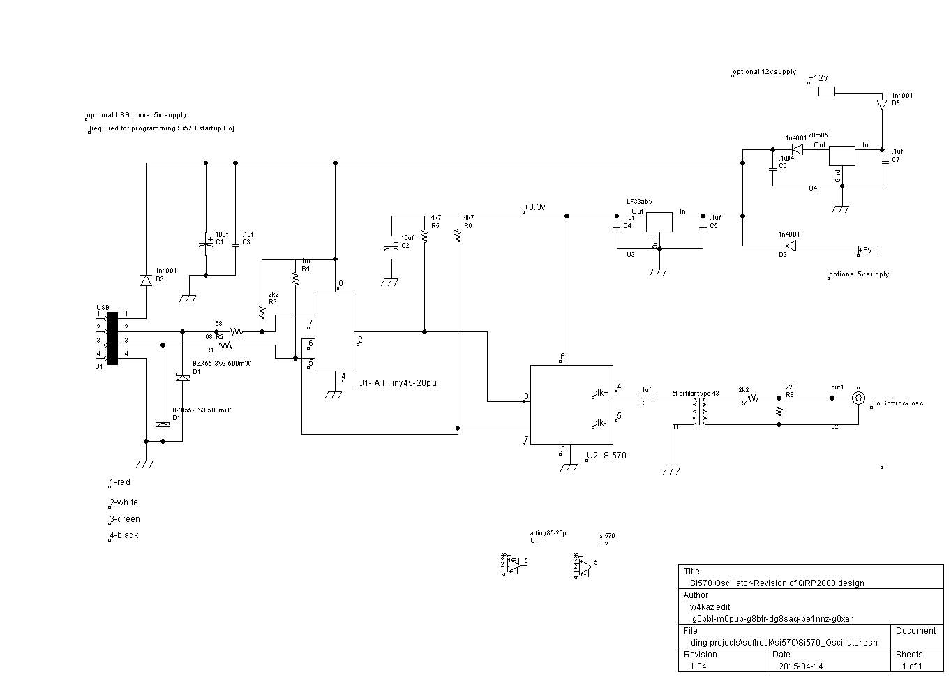
The oscillator itself is pretty simple, and is the bare essential hardware required for re-programming the oscillator for a needed single frequency to use with a Softrock Lite II rx.  It is based on what I saw in the the schematic of the Softrock Ensemble RX, nothing original, just pared down and hijacked from the original Ensemble design.  The Si570 part itself is the bulk of the expense of the oscillator, and the cost of the Si570 chip is almost as much as the Softrock Lite kit itself.   The oscillator signal is fed into the divider through a 10K voltage divider as in the Softrock RX.
So why an Si570 Programmable Oscillator ?
The RX Ensemble kit is a viable alternative expense wise.  It really depends on the intended usage.  Using separate Softrock Lites as single band CW skimmers leads to the choice of a programmable oscillator for customizing the center frequencies, especially for the high bands.  The method used for 20m using the third harmonic seems to result in a decrease in dynamic range.  That results in an increase in false mirror images being reported to RBN by the CW skimmer as actual spots.
Using the Si570, the oscillators can be set at the frequencies needed by the Softrocks, i.e. 4 times the center frequency.  (for 96Khz bandwidth the oscillator would need to be: 20m=56.188, 15m=84.188, and 10m=112.16).  A programmable oscillator also allows switching from 96Khz to 192 Khz bandwidth(20m=56.38,15m=84.38, and 10m=112.38).  Keeping just the bottom half of a 192Khz bandwidth CW skimmer would at a minimum eliminate at least 50% of bad mirror image spots.  There are also likely to be fewer stations CQ’ing below the “.096” section of a band(e.g., most often there is not so much regular CWactivity above 28.096 as there is below).  That is the idea anyway.
The Si570 Programmable Oscillator Prototype:
The first version is deadbugged on a bit of board scrounged from the parts bin. Â Not many parts, but a bit more PCBÂ real estate would have been better. Â Functional rather than esthetic. Â The USB connection is via the usb cable end clipped from an old computer mouse in the parts bin(unlabeled black coil in left of photo). Â Â “Engineer the possible”.
Si570 Programmable Oscillator board for 10m Softrock CW skimmer
Testing the original prototype board pictured resulted in three build mistakes to debug:  a missing 5v connection to the ATTiny and the reversal in polarity on both zener diodes across the USB data pins.  These mistakes prevented function without damage to the components.  After correction of the build errors the software was able to function with the Si570 as needed for both programming the oscillator(‘startup’) frequency and running as a stand-alone oscillator.
The Si570 when programmed for 112.36Mc was found to have an actual oscillation at close to 28.090 exactly from the Softrock divider, as measured with TS-590 and Elecraft K2.  This was with the oscillator inserted in-circuit as the Softrock Lite oscillator via a transformer(5 bifilar turns on a type 43 torroid core) and a 2.2k resistor.  The frequency is very consistent and stable when the power is cycled on/off.
Easy measurement of the actual frequency in place is good enough for initial setting up of the skimmer software. A few KC either way will make little difference in a CW skimmer set-up, as final adjustments were done in CW skimmer software to put the skimmer signals ‘on frequency’.  In this case the CW skimmer center frequency is nearly identical to the Si570 programmed frequency.  That has not been the case with the versions using ordinary crystal oscillators, those having a bit more drift off their nominal value.
A new Softrock Lite II is the 10m test bed, with 15m revision to follow. Â These two bands suffer the most from poor dynamic range and false mirror images. Â The 15m oscillator also has a nasty tendency to drift with temperature changes. Â If the modified softrocks perform as desired it will be time to pair these two bands with the best of the sound cards available. Â That will be a separate game of trial and error. Â The 20m softrock skimmer may also be retrofit, as using the third harmonic for the softrock center frequencies seems to adversely impact the dynamic range.
Photo of 10m Skimmer at W4KAZ
As an aside, the first 10m center frequency chosen was 28.060 into a 192Kc bandwidth sound card. Horrible choice, as it was close enough to the 15m harmonic that interference spikes were present on both bands every 900hz. Â Resetting the Si570 oscillator to place the center Fo for 10m at 28.080 greatly reduced(but not eliminate) the problem. Â Currently set on 28.090 as of 20150414. Â More tinkering required, and migrating the 15m Softrock over to an Si570 oscillator may help.
The current Skimmer package for 20m, 15m and 10m. 20m and 15m will likely be re-worked to use Si570 Programmable Oscillator.
Si570 Programmable Oscillator UPDATE, 2016-11-08
The Si570 oscillator as described was perfectly usable in this application. Â However 10m and 15m performance was was poor on the softrocks, the primary difficulty being a low dynamic range. Â This is indicated by mirror images that appear when SNR values on the actual signals were higher than 35dbSNR.
The most useful work around for this problem is to scan at 192Khz sample rate, and only use the lower half of the sample for the CW skimmer. Â Using the upper 96kc might be easier, as the center frequency could be set at 28.0Mc and 21.0Mc. Â The latter may ulimately be the best approach. Â There are unlikely to be any useful signals below the bottom of the bands, and those could be readily discarded as false or otherwise unusable(i.e., out of band).
LINK LIST, Si570 Programmable Oscillator :
W4KAZ Schematic
Schematic for W4KAZ version of Si570 Programmable Oscillator
W4KAZ BareBones Parts List (PDF) (HTML with links)
G4ZFQ has  RightMark test data for a high end Xonar D2X card, as well as several others.  An internet search found other RightMark tests of several other Xonar cards, all of whose test data show curve trends remarkably similar to those of the D2X, albeit with somewhat worse IMD, spurious, and noise figures.
The curiosity is the test data shows a roll off on the frequencies above 50khz. Â The nature of the loopback test is an issue, but it also seems likely that using a sound card as the source may be having an effect on the test results at the higher edges of the sound card frequency response. Â But signal generators as input to the tests shows the same general trend. Â SDR at wider bandwidths pushes at these edges of a ‘sound’ card’s ability….So perhaps the SDR software is compensating for the expected performance drop-off at frequencies above audible levels?
The Test- (Pertinent Excerpt from list post):
Having not yet thought of a better way to do a meaningful real-world test on the sound card with what is available in the KazShack, I fired up the 80m softrock on the xonar DX.
Test condx:
Transmitting a cw signal(a string of dashes at about 18wpm) at 5w into a dummy load on separate radio, noting the SNR readings obtained by CW skimmer from the SoftRock center frequency(353395x) to its upper limit. With the xonar DX set to 192khz scan rate, the actual upper limit on the readings was 3629.60. SoftRock connected to normal antenna system, a NE facing K9AY with W7IUV pre-amp. In summary, a sound card test using the SoftRock system as input source.
fq….—-SNR(dB)
3534.5—-42
3543-3593-42-40
3603——37
3613——35
3623——32
3629.6—-36
After CW skimmer collected a bit of data, the SNR readings above 3600 improved to 37-39.
So the worst case for CW skimmer(as currently configured) using a Xonar DX is being 6db less sensitive at the upper edge of the 192khz bandwidth than it is at the center. That is actually a lot better than I expected for an audio device pressed into service outside normal audio ranges (and I already liked the Xonar DX).
My curiosity is now nagging me to run the same tests on all of the other in-shack cards more methodically at their maximum scan rates(mostly 96khz), and to find a lower level outside signal source. I’ll try to recruit a fellow in the near field who will better be able to generate a low level test signal.  It would be useful to see what happens at the band edges when the best copy close to the center of the SoftRock’s scan range starts out at 20dB, 10dB, or 6dB SNR.
But with the WX here improving, all of that might not happen for several months.
😉
By w4kaz, created on 2012.07.21 at 18:26:11 | last changed on 2018.06.01 at 15:25:31 |
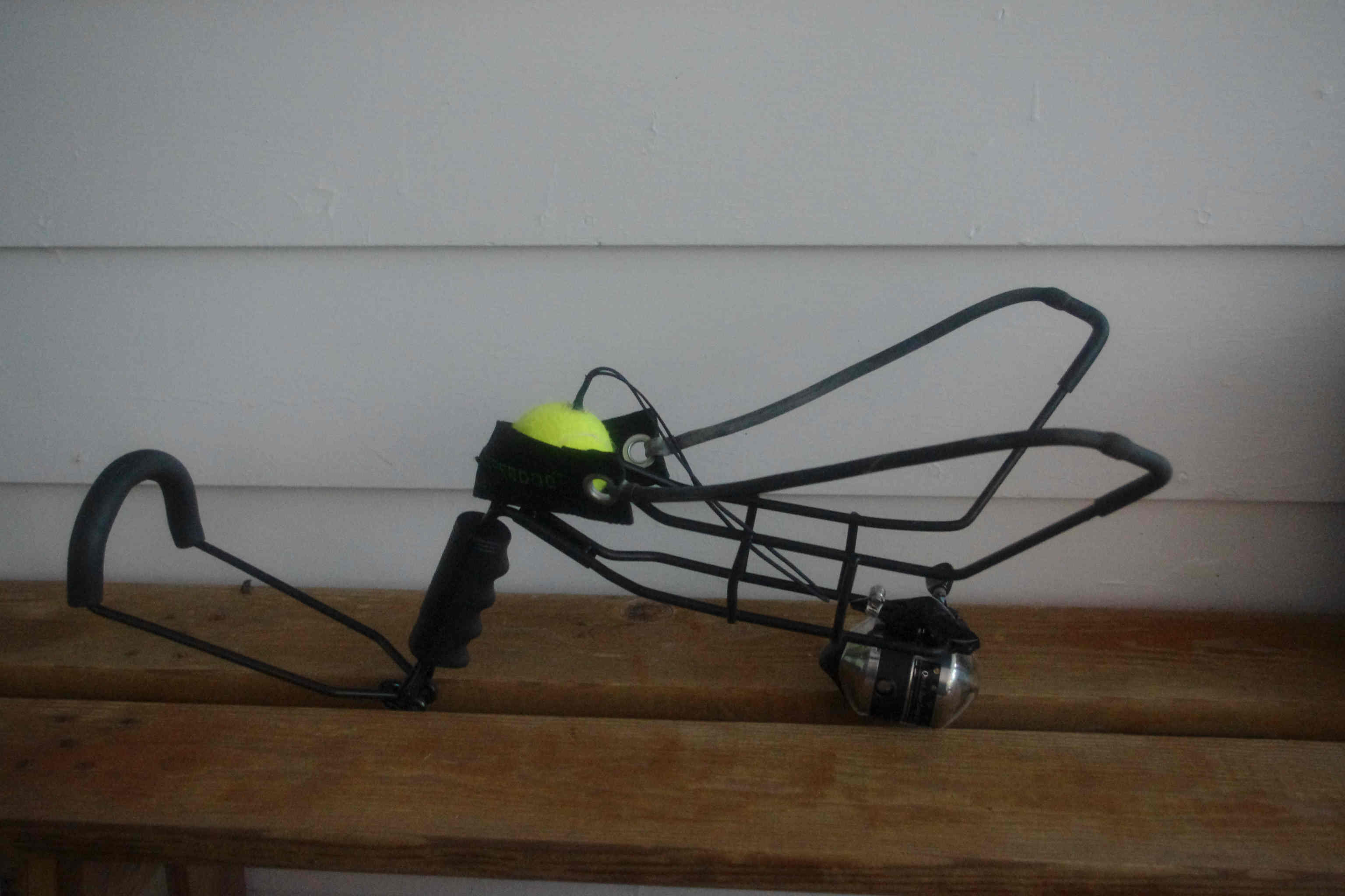
Ran across the hyper dog ball launcher a couple of years ago, and the potential for re-purposed applications as an antenna launcher for hanging antenna supports seemed obvious.  It is not as much fun as a pneumatic launcher, but it sure is easily understood by any boy of 8.  No air pump required.
The modified hyper dogÂ
The normal slingshot type Wrist-Rocket/Crossman slingshot launcher has served the purpose for years, but not always without problems. Â A 1-oz(28g) lead weight works, but not without a relatively high rate of mis-fires, line tangles, and “Oh S**t!” moments. Â The hyper dog is a lot less likely to draw whining complaints from those inclined to wring their hands and moan about things that don’t really concern them..”See, its just a tennis ball. Â Now p**s off!”
The hyper dog has a much larger pouch designed for use with tennis balls.  A slight bit of hacking to the hardware gives a nice re-purposed tool for lofting lines into all of those beautiful deciduous biological antenna supports lining the back yard.  So far it has been a lot more reliable in actual usage than the ole trusty Crossman, although Field Day proved its not impossible to Dork Up.  [You Know Who You Are….lol]
The reel deal:
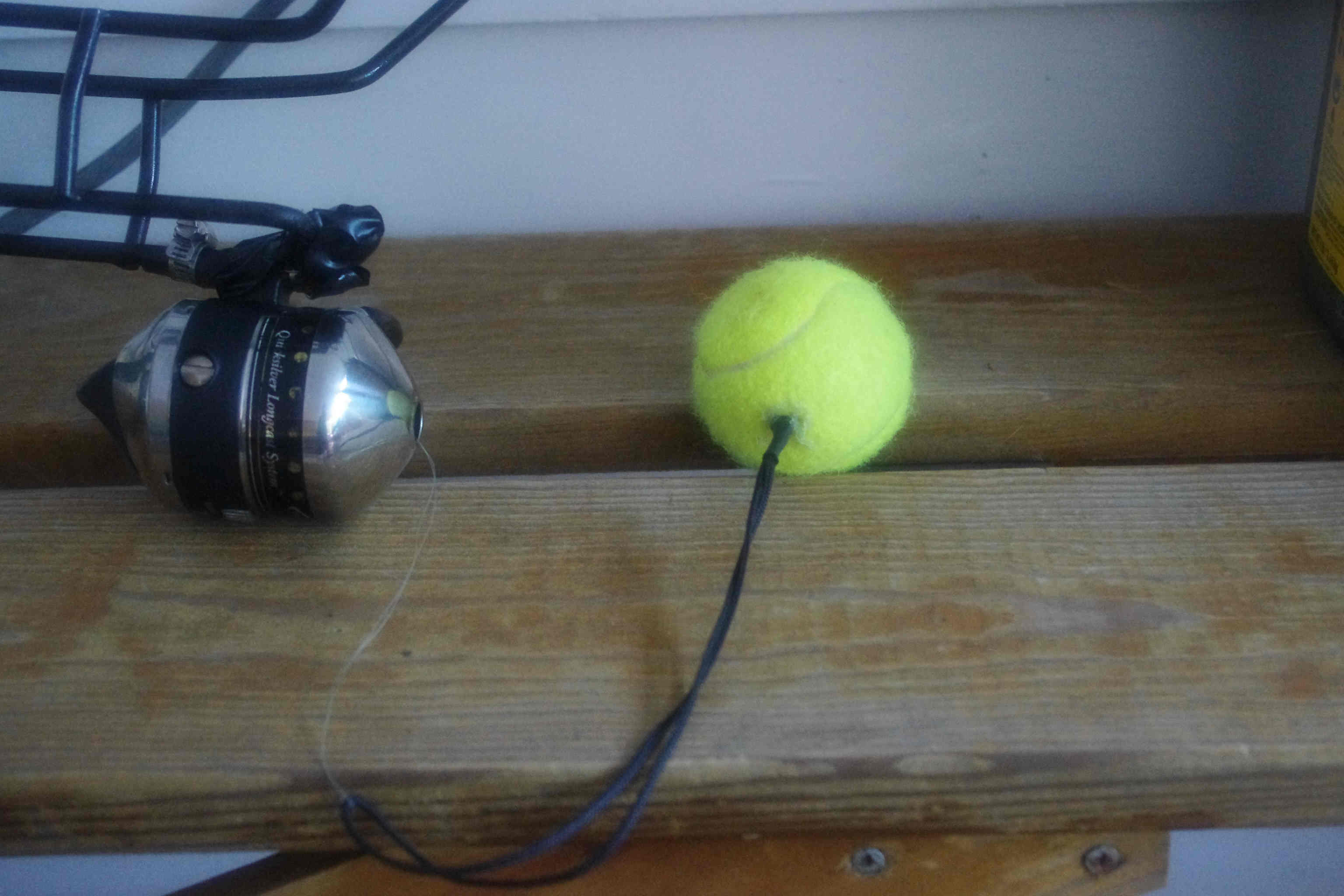
Here the body was altered by adding a cheap spin-cast zebco reel picked up for $2 at a yard sale. A spinning reel or open faced casting reel might be better, but I have used the zebco’s since I was 6yo.  Being more familiar with the Zebco quirks and limitations is useful. For most, a spinning reel is probably the best option.  10 or 12lb test line has proven the best choice over the years – light enough to fly, strong enough to pull, and not impossible to break if it becomes hopelessly snarled at altitude.
The reel is simply attached below the ball carrier with a couple of hose clamps. Â That was later wrapped with an ugly mess of electrical tape just to reduce the number of exposed sharp edges.
Yes, the tennis balls work FB.
To modify the tennis balls, they were  just drilled with a 9/64 bit. A loop of 1/8th braided nylon cord is secured to a small hardware store drywall toggle bolt/spring bolt. Then just cram the bolt/cord through the hole, reaming the hole out slightly if needed[leaving most of the loop of cord hanging out!].   The base of the cord is sealed at the hole with a goop of liquid nails or hot glue or some-such.  The loop of cord is about 6 inches long(~150mm), and the spring bolt serves the same purpose it normally does by providing a large area preventing pull-out.  After drying completely – good to go.
The tennis balls seem to be a good compromise between weight and a non-destructive & non-threatening projectile. [Just don’t try to pull them back up through the tree-too fast!].   The ‘trick’ to success with it seems to be making sure the cord on the tennis balls clear the end of the slingshot. It seems to work best when the corded end of the ball is facing  up(i.e., at the top of the pouch when pulled back for a shot).
What’s the catch?
The only genuine problem I have with it is that it has a “long draw”.  Being impishly short my arms are not long enough to get the maximum performance out of the rig. But despite that it works much better than the regular slingshot with fewer snags and mis-fires. It easily sends the tennis balls up to about 90 feet(~30m).  The canopy here prevents anything higher, so no real top-end found yet.
I suspect golf balls would be the ultimate high-flying projectile for rural locations. Too much window glass and nervous-Nelly neighbors around the home QTH for me to try golf balls here.  A day-break early morning experiment for the future…. 😉
There is somebody here on the east coast marketing these re-branded as antenna launchers, and asking $80. Â See Radiowavz Hyper Hanger, now $90USD….
By w4kaz, created on 2012.07.06 at 10:42:06 | last changed on 2021.05.06 at 21:08:01 |
Created a page of links and several related pages of information on the ongoing construction of the CW Skimmer station at W4KAZ.
Because of the nature of the blog package used for this website, it is easier to save this skimmer related info on ‘pages’ rather than as a “post” because it seems like a project that I’d like to have semi-permanently documented, and have the documentation easily found. Whooop…there it iz….Incomplete, but slowly growing, and probably to be frequently edited in the short term.