End Fed Half Wave Experiment – Part 1
Construction
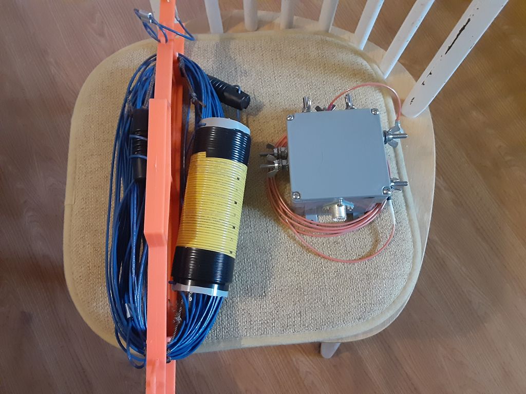
The Initial cut of the antenna and the completed feedpoint enclosure.
Having looked at many of the articles available on the WWW, I wound up favoring the design well documented by G0KYA, Steve Nichols. When modeling the antenna I started out using a coil value of 67.5uh. Then I ran the model using the appropriate value of impedance at each given frequency. The coil as shown above is about 63 turns of 16ga solid insulated wire on a plastic coil form of just over 2 inch diameter. That was right at the limit of the amount of wire I could lay down on the available form. The completed coil resonated with a handy 22pf capacitor at 3.855Mhz, which calculates out to an actual inductance of close to 77.5uh. With the coil value known, I re-ran the model to tweak the initial guestimates with actual values of XL for the model’s load. Then cut wire for the 40m leg as well as the 80m tag end. BEFORE tuning wire lengths are long, 71 feet and 15 feet(about 21.6 meters and 4.5 meters).
Inductor
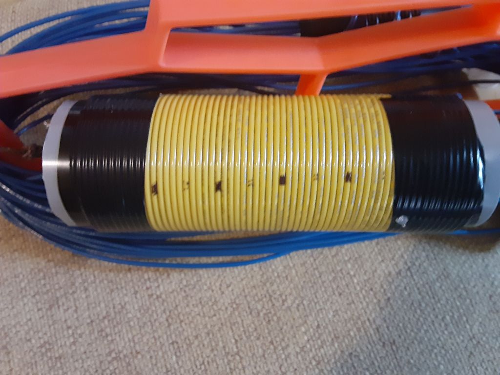
77.5uh inductor, ~63 turns of 16ga insulated wire wound on a 2 inch plastic form.
The coil form used seems better for RF than PVC pipe, and is a one-off that happened to be in the parts bin, original source un-remembered. I gave it a run in the microwave, and it showed little heating. It’s other quality is it is 1/16 wall thickness, so most of the weight is the winding. The coil is just over 6 inches in length. The second choice for a coil form was going to be fabricated with a few layers of fiberglass and epoxy laid up on some sort of removable former. The measured value is only about 2/3 of the specified 110uh from the G0KYA document(original designer-????), but it comes down to the trade-off question again. This 77.5uh coil should provide 3400 ohms XL at 7Mhz. Hopefully that will be sufficient to isolate the tail. Actual testing should be interesting.
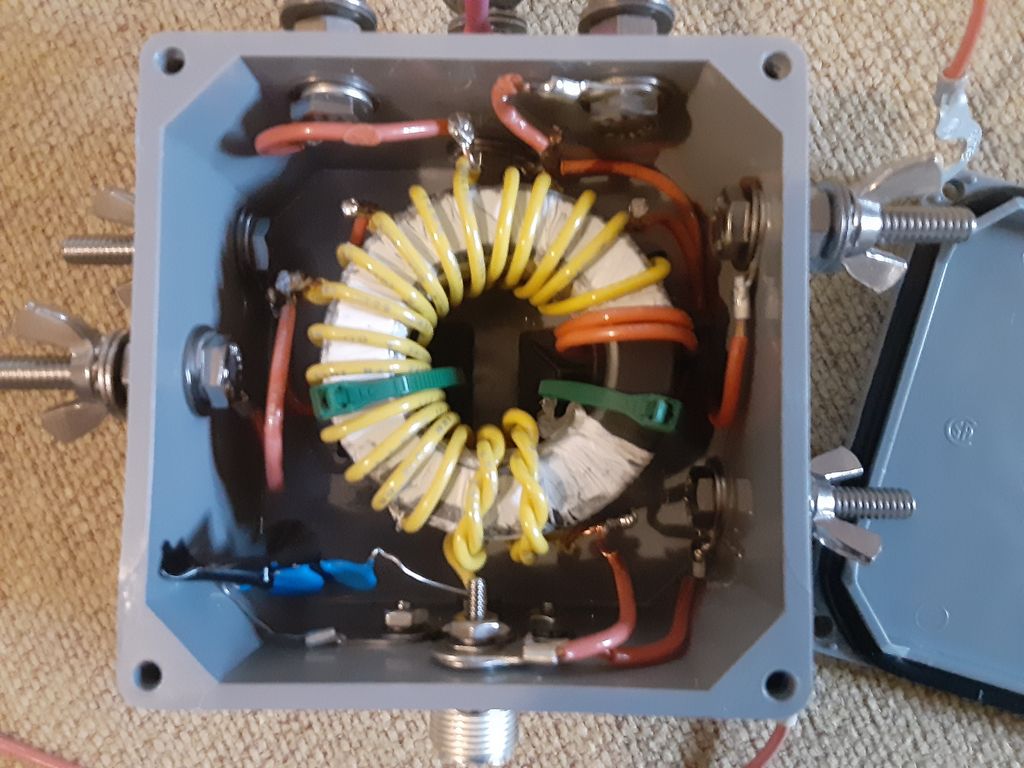
This is the completed transformer installed in terminal box.
It has two ft-240-43 toroids together with a two layer cover of teflon tape to make it more slippery for winding. It is wound with a 2 turn primary and 20 turn secondary. Taps are placed on turns #9, #11, #13, #15, #17 and #20. For the capacitor I used three TDK 330pf 3kV 5% ceramic caps in series. I went that route simply because I had more of that value cap handy than either 220pf or an actual 100pf. There are no crossover turns – that seemed counter productive for multi taps. I would have wound the secondary turns more tightly but needed to loosen the turns up some just to fit it in the box and attach the taps.
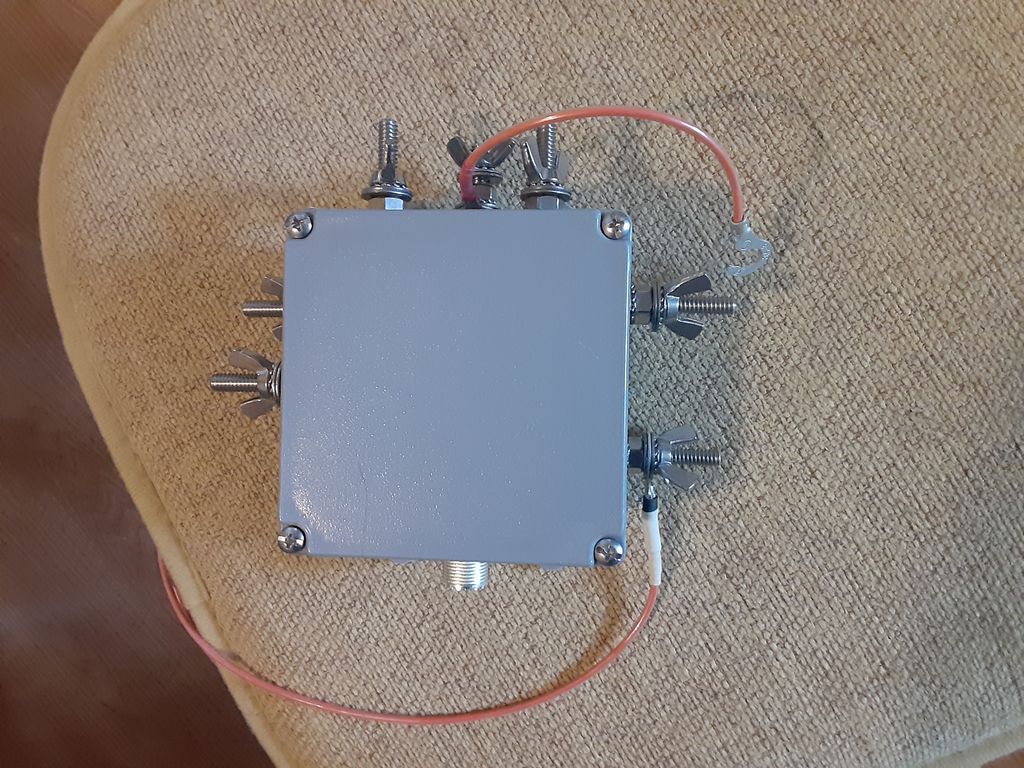
Closed box showing tap wire on top and counterpoise on lower right.
The feed point box is an ordinary Carlon 4x4x2 terminal box. Feed thru studs are all 1/4 stainless hex bolts. I expect to attach the antenna to the 10:1 tap(located top center) and use a jumper to short down to the lower impedance taps as needed for best match rather than have the high impedance taps float. The stud on the bottom right is the ground/counterpoise attach point. If nothing else, the multiple taps provide handy places for extra hardware to replace wing nuts fumbled into the sand.
Leave a Reply