Radio W4KAZ Thanks for stopping by the virtual KazShack. Feel free to comment - I often approve them.
|
By w4kaz, created on 2025.07.29 at 11:18:18 | last changed on 2025.07.29 at 11:28:13 | 2025 ARRL Field day at cape lookout was more of a fun trip to work out bugs from my failed CQ WPX camp trip.
Using a different antenna tuner with the same antenna from WPX presented ZERO issues, so now I am more curious about taking a closer look at the antenna tuner as the source of the problems. The radio used for FD was my Elecraft K2. Everything else EXCEPT the tuner was the same set up as used for WPX.
Result: FD, everything worked. WPX, transmit issues out the wazzoo and I bailed out before the contest started.
Ahem.
Since the trip was also an extended birthday party, spent a lot more time on smoking cigars and sipping really nice whiskey. Despite that, still managed to cage 232 QSOs. As a change of pace I ran packet spots, and had fun just punching cw spots. Total operating time was about 8 hours, with 3 hours at the start on saturday afternoon and the bulk of it Sunday morning. Both periods terminated by food, whiskey, and cigars.
Sensing a theme there….
Some photos in a slide show from the field day hootch: http://w4kaz.com/images/2025_fieldday/
By w4kaz, created on 2025.03.15 at 19:27:17 | last changed on 2026.05.04 at 20:52:25 | Looking at a few of the promo vids folks have posted so far about the Pota33H mast I decided to take a chance on it and the order arrived late last week. On first look I thought it might not be long enough to stretch to the 30-ish feet, but I underestimated the strength of the carbon fiber. For its short length it has a lot of sections inside, and the top section is about 1/2 inch diameter tube. Thicker tubes are stronger than thinner. The carbon fiber provides a lot of strength in a much thinner level of material, so it should be just fine. I expect it will have less flop/droop than any of the fiberglass masts. But the folks who got it made should be happy, it seems to check all of the design goals any backpacker might have for compact, lightweight, and strength.
It did have a couple of caveats for my own uses. If the mast were a full 48 inches I would like it better, but it was designed for its short collapsed length. The second caveat is more of an impact for my own purposes. The base piece at the bottom of the mast is heavy duty, and quite thick. The end cap is thick and sturdy. So thick that as delivered it is just slightly too large to fit in one of my favored mount methods, a trailer hitch post holder.
 The end cap from the pota33H after filing is about 60mm diameter. It fits into one of the hitch mount post supports, but not the other. |
 The hitch mount that does not accept the Pota 33 mast appears to also be about 62mm diameter. Perhaps it is out of round? Thicker walls? Will need the micrometer to find out, the two different pole receptacles appear to be the same size to eyeball mark 1. |
 The hitch mount that accepts the Pota 33 mast is about 62mm diameter. |
 Pota 33 base fits for this hitch mount after a bit of judicious filing |
 Pota 33 base is too fat for this hitch mount |
 The truck hitch receiver with a step extension that supports the telescoping fiberglass mast. The mast du’jour is the Jac-kite 31 footer. Plus assorted extra junk in the truck bed. |
After trying the mast in both mounts it was clear it was very close to being able to function in one of them. After a few passes with a file around the widest part of the pota33h’s base cap, it was able to just barely slide in to the hitch mount. That will make deploying portable a bit more convenient. Kinda hate putting the file to a massage brand new sort-of-pricey mast, but WTF. Not like I was sending it back anyway.
Also, the pota33h should be FB for use in the screw in earth anchors I use for the beach side deployments. As long as it works with those its worth trying.
The unknowns now are: What it will do with a real antenna attached? Will the friction fit hold in the wind? Will the friction fit hold an antenna without collapsing in the 20 knot winds common on Cape Lookout? Will the carbon fiber be better than fiberglass when stressed? Will the thin wall carbon fiber tubes crack and split, compared to fiberglass more or less likely? Will sand prove to be a bigger problem for this mast than others? Will it really be less floppy than its fiberglass predecessors? Will sand cause it issues? Will it have difficulty being lowered after a roll in the Cape Lookout sand? TBD…soon!
Future post on “mast roundup”?
By w4kaz, created on 2024.07.05 at 14:20:57 | last changed on 2025.05.28 at 17:00:09 |
Solo FD for 2024, once again a camping trip to Carolina Beach state park(POTA US-2722).
The station
Arrived late Thursday afternoon and set up the campsite, had an early evening meal, and a relaxing cigar.

After a mixed night of broken sleep, started setting up radio gear and antennas on Friday afternoon. The station was an Elecraft K3 and an MFJ versa tuner as the antenna switch/swr meter.

Tried out a new computer, which flopped big time as it could not connect to either the radio of the winkeyer. Forgot to load the FTDI drivers on the target laptop beforehand, so whipped out the old-n-busted laptop for the duration. Old and busted has charging issues, but it worked well for intermittent sessions with charging during off time breaks. It was easier to use the known computer than waste time on the unknown.
Having decided beforehand to operate mostly during daytime hours, no antenna for 80m was set up. Two trap dipoles were hoisted, one for 40m/20m and the other for 15m/10m. Both installed on separate telescoping fiberglass masts as inverted vees. The masts resulted a height of about 27 feet(~9m) for the centers of the antennas, generally favoring the NW direction. Ran a few test strings and RBN results looked decent.
Its-not-a-contest-its-an-event
Saturday morning had enough time for a good breakfast, a supply/ice run to the store, and plenty of time left over for a few shakedown qsos. Was growing tired as 1800z approached, so got off to a slow S&P start. After a bite to eat and a short walk to stretch out the legs back to it for several more hours. 15m was good at the start, and 20m was good into the evening. 40m was good too, but with 20m flowing it was more interesting to stay there. Bailed out for much needed sleep at 0230Z.
Morning brought another slow half hour start at 0930Z. Slow but steady runs began soon though there were a lot of S&P periods mixed in. Started Sunday morning on 40m and began sweeping up 40/20/15 as the morning progressed. 15m was not nearly as good Sunday morning, but 20m kept improving. Strong finish on 20m. Finished up with about 475-480 Q’s.
After a short break station teardown took a couple of hours. The antennas came down first to keep the work in the shade. The station was torn down and packed with an eye on using the same setup again portable at the end of July for IOTA 2024. Antenna selections for that may change based on site location,WX, or any other wild hair that might manifest after 30 days delay. An EFHW for 40m would have been used to add 80m. I had an 80 FCP variation ready in that case, and the 40m EFHW functions as the 80m 1/4 vertical element. That configuration requires a switching of the EFHW feed point to one dedicated to the 80m vertical. Looking for a way to use relays for switching within a single box.

Portable and CAMP notes
The camp site used was almost ideal for a single station and limited antenna set up. It would have been possible to squeeze in another EFHW or dipole easily. The 4runner served as sleeping quarters with an easily detachable screen awning for rain and bugs. The screen awning was relatively easy to detach/attach to the vehicle for ice and food runs, both easily available right around the corner from the park. It would have been substantially LESS convenient to detach the rain gear in bad weather, something to be planned for in the future. Still better than using a ground tent, or one of the newly popular roof mount tents. Too old for either of those to be worth while anymore.
Food convenience is now an issue. Just don’t see much point in being very picky about trying to store any specialty items. Roll with convenience over healthy going forward.
Another drawback to the location is…..the location. The park itself is quite nice, but the drive is not a lot of fun. Maybe another park in a more rural area would be a better choice if another suitable camp site can be found, although the nearby supply resources are useful and convenient at Carolina Beach.
The weather was hot but tolerable, and the rain mostly cooperated by being light and timely. No lightning for a welcome change. The only WX negative was when a shower came during a food run, making re-setting the screen tarp a bit of a mess.
When the sleep schedule is broken, naps are refreshing. Just do it. Sleep when tired makes the other waking hours more interesting and elevates alertness levels.
MOAR PHOTOS *link http://w4kaz.com/images/2024FD_web/
SCORE RECAP

FD W4KAZ W4KAZ
By w4kaz, created on 2024.04.01 at 14:11:02 | last changed on 2024.04.01 at 14:56:26 | Last month we finally got a chance to take the radio for a spin to work the NC QSO party from a few parks. A ‘few’ parks turned into two parks, but I did learn a few things. The weather in my area turned out to be perfect for a nice ride to a couple of portable operating areas. Comfortably cool temps and crystal clear skies.
I decided to approach the trip as an Out-and-Back. Drove out to the first park with intent on making stops to set up the portable antennas at each location. Had just barely enough time at the first stop to get set up before the 10am local start. Then things quickly went sideways.
The Station
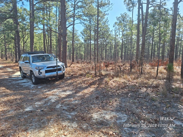
Used a hitch mounted mast receptacle to hold the antenna mast, a 32 foot telescoping fiberglass pole. The mast supported a 40m/20m trap dipole, which I probably damaged by breaking a partially corroded wire on one of the traps. Ends were tied up on some of the nearby coniferous biological antenna supports. The station itself is an Elecraft K3 powered by a 100ah LifePo4 battery, on trickle charge from a 100w solar panel on the vehicle roof rack. All set up on back seat of the vehicle. Parked in the shade because comfort is more important than charging the battery. Location numero uno was at McKinney Lake State Fish Hatchery Pota k-8010, Richmond county NC. Unfortunately no photos of either the station or other sites due to ‘plan divergence #2-Lost Phone!’.
Diverging from the plan
Maybe a bit over-ambitious. The first event occurred when the antenna suddenly lost its nice low SWR on 40m. It is a 40m/20m trap dipole that has been in use for a couple of years. Made just a handful on 40m to start then moved to 20m. The antenna was still OK on 20m. Curious. After a bit I dropped the antenna to try to debug the 40m issue and noticed the wire coming out of the trap to one 50m leg appeared corroded. Wasted too much time fiddling with antenna instead of operating. Wire corrosion plus over-vigorous installation Mistake #1.
After burning too much time at the first location, moved on to POTA#2. Ate my lunch there an could not find phone. Spot#1 was just 6 miles away, so retraced to POTA#1 to see if I had dropped it there. No Joy. Mistake#2
Decided to skip spot#3 and drove directly to spot#4, Lee State Game lands, Pota K-06920 in Lee county. Set up the 40m EFHW, and had decent runs on both 20m and 40m. Success! Neither 10m nor 15m were delivering, so skipped any time there. This had the sun beginning to fall below tree line, so packed up the kit and moved to spot#5. No photos taken, still had not found phone.
Spot#5 turned out to be occupied, and no other locations in the pota had been scouted. Mistake #3. At this point I mostly bailed. Parked the car at home in driveway for a handful of Q’s on a hasty 20m vertical(non pota). Then ditched entirely for food.
Damaged goods:
The broken antenna is going to be replaced. A functional backup will also be added to the travel list. The real downside did not show up until later, when the logging computer quit taking a charge. Very likely RF damaged. Bleh.
Lessons
What was pounded in again is that wasting time during the event is costly. ALWAYS have a backup. The “lost phone” was not lost but had slid down between seats inside an invisibility cloak. Found that at home by dialing the number. Not knowing was rain on the parade.
- Need to examine the locations as planned to have an alternate site ready.
- Need a few dry runs setting up to get a hard figure on how much time is needed. Pota practice sessions!
- Need to research better to determine transit times between sites.
- Use the firmer times to budget time on each site.
- Be more flexible.
- If something craps out, HAVE A PLAN B
- If the ANTENNA craps out go DIRECTLY to the backup. Do NOT fart around with the broken antenna, it can be dealt with later.
- Plan on more CW.
Taking the time to activate LEE and RIC was worth the effort. It should be feasible to easily activate four different counties/Potas as a portable in the 10 hour period. More than that would require more research or an area with a higher concentration of Pota entities. Travel time is an issue. Operating from POTA entities was also worthwhile, and the first time scout of the sites was useful for future POTA activations.
By w4kaz, created on 2024.03.18 at 12:52:01 | last changed on 2024.03.18 at 13:37:30 | A really cool RBN mapping site:
Check out the work of HA8TKS. Good format, centers an azimuthal projection on the searched call sign with lots of options. Lots of options to play with, can be used to list the spotter station or see stations that are spotting a caller.
EXCELLENT!
https://dxcluster.ha8tks.hu/azimuthal_map/index.php?c=W4KAZ&t=de
By w4kaz, created on 2024.02.26 at 16:08:15 | last changed on 2024.02.26 at 16:08:15 |
Fun hints on setting up writelog to key the SSB memories on the Elecraft K3.
Check the ini file for the K3 commands section:
[Elecraft_K3_commands]
Macro_10=SWT21;
Macro_11=SWT31;
Macro_12=SWT35;
Macro_13=SWT39;

Then set up each contest for the %gk10,%gk11,%gk12,%gk13 in the SSB function keys(I choose to go with F1-F4)
See the whole K5ZD info…….https://k5zd.com/setting-up-writelog-to-send-k3dvr-messages/
By w4kaz, created on 2023.08.05 at 16:10:03 | last changed on 2024.12.03 at 21:23:38 |
Sand and Radio
What could be more fun than dancing the biting fly dance to set up antennas for playing radio in the sand and sun? Hmmmmm.
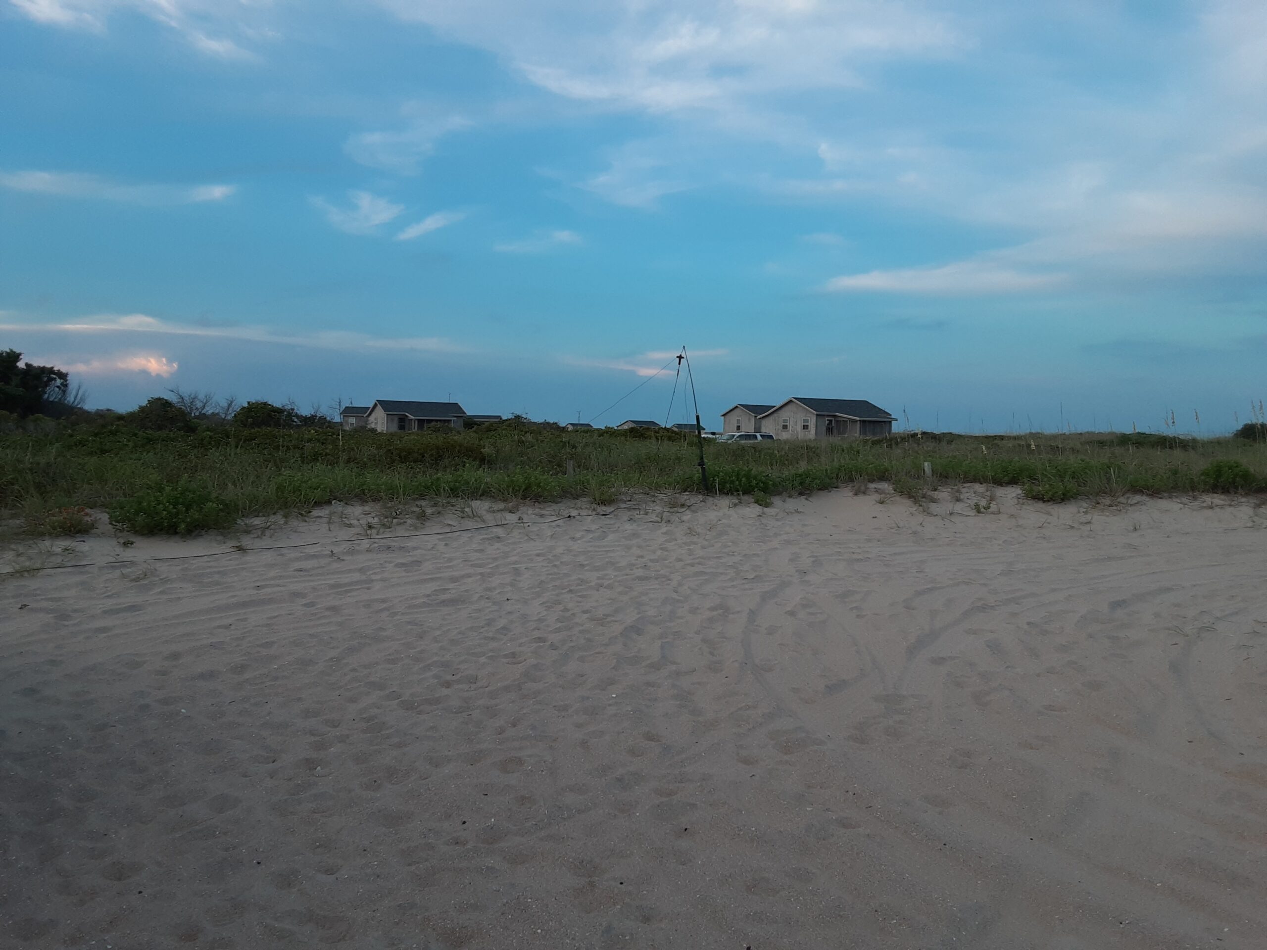
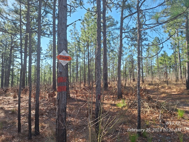
The weather on the south core banks(‘Great’ Island) gave glimpses of gloom but mostly cooperated very well for a change. Arriving at the cabin about 1pm local(1700Z) allowed us to unload gear and set up masts and antennas in the normal sunny sandy heat.
Photo Album w4kaz M/S 2023 IOTA photo album [Most photos by N4YDU]
Antennas and Station
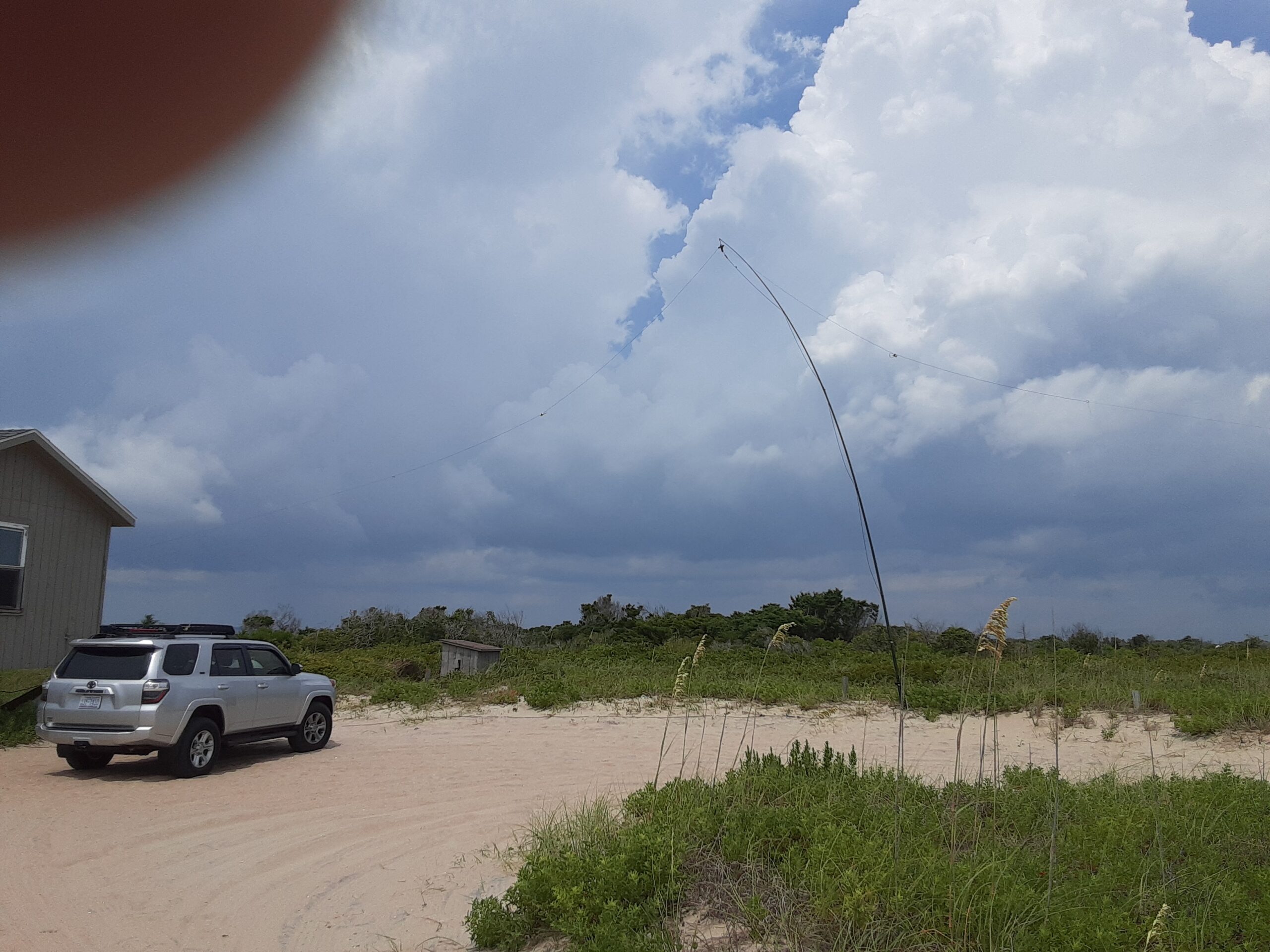
The main antenna was a 40m/20m trap dipole, with a 15m/10m dipole as a second. We also set up a 40m EFHW that allowed use of its radiator as an 80m inv L vertical. We also set up a BOG as an rx antenna using about 200 feet of wire and a transformer. The BOG made use of the generator hut’s ground wire. The EFHW was fed on 80m against an 80m folded counterpoise.
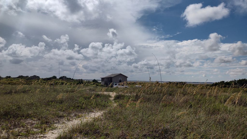
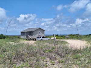
 2023 W4KAZ M/S Iota – Right/background is the 40m/20m trap dipole on its telescoping mast. Left/foreground is the mast to elevate the end of the EFHW. The generator ground was free because power was supplied via LifePo4 batteries. These were supplemented by 200 watts of solar cells once they got plugged in again after being knocked loose. The main radio used is an Elecraft K3.
Contest
The operating was at times interesting and at time tedious. Pretty much normal for IOTA from NC. N4YDU started off on 20, but quickly moved to 15m upon finding it more productive. That was one of the more interesting things, as 15m has been a dry hole for the past few years. We swapped off every couple of hours or so after that.
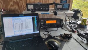 2023 W4KAZ M/S Iota Station layout The normal mid day doldrums were supplemented by calling both CQ IOTA and CQ POTA and giving out the park K-0683 along with the IOTA exchange. 20m SSB started to pick up during my 2000Z shift. After that I was happy enough to turn the keys over to N4YDU for some of that world class operator stuff on 40m CW. One of my highlights is listening to N4YDU pull callsigns out of 40m bedlam at 30wpm. One of N4YDU’s highlights was moving W1BBB across 9 band/modes for his unique mult. Thanks to W1BBB for having game!Â
Early nightÂ
The evening was capped off by the unexpected termination of the logging computer around 0330Z. The battery supplying voltage had reached its limit and cut off power to the hub. Both of us were ready for some sleep, so we pulled plug and prepped for incoming weather. The weather arrived about 0600z, lighting up the sky and rumbling half of the team to gloomy awareness. 😮
N4YDU capped off the morning chasing mults and possible 15 pointers around. W4KAZ snoozed.
It ain’t Over….
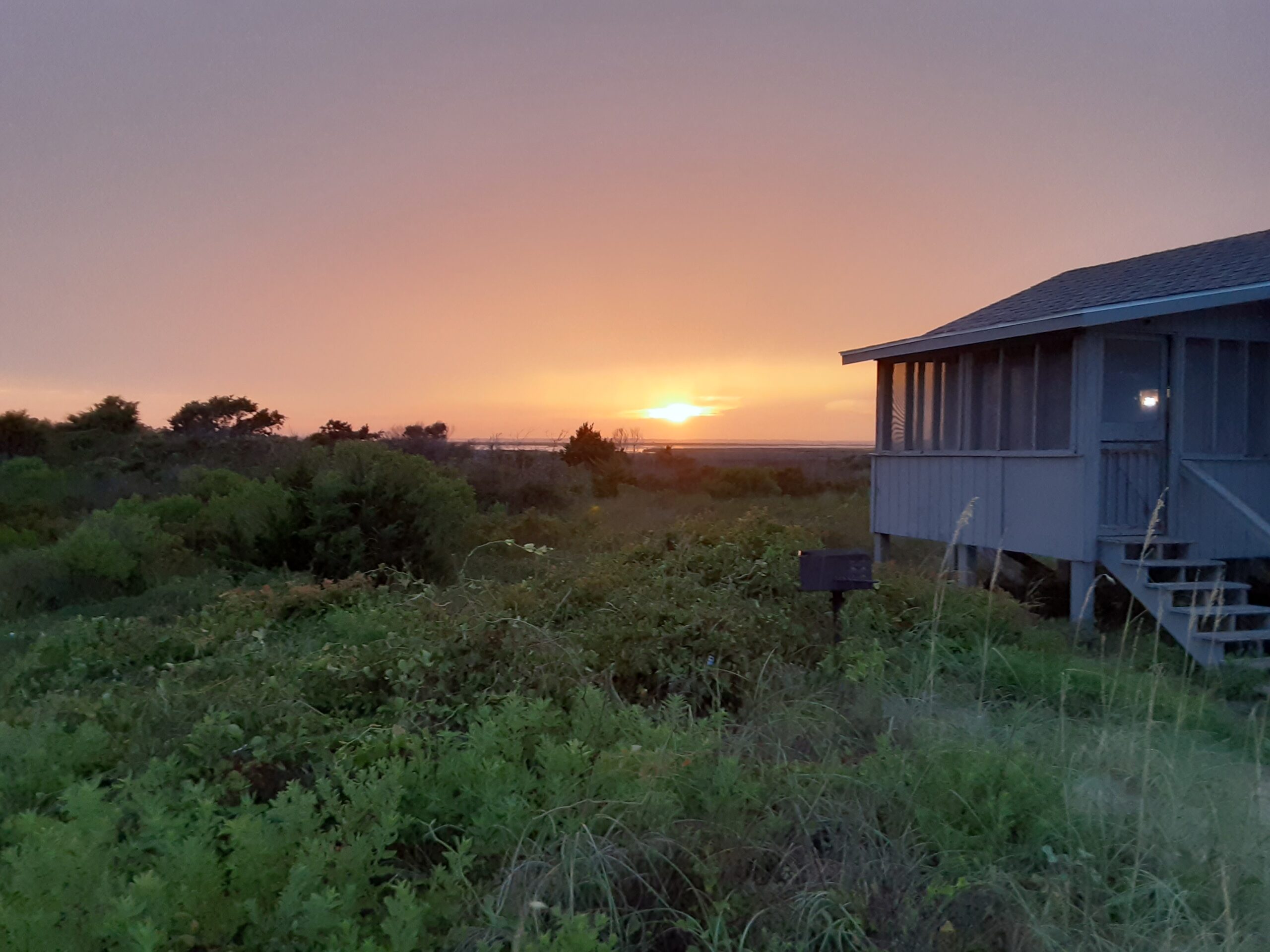
After the 1200z end breaking down gear goes much faster than set up. Plans for possible extra POTA operating were ditched in favor of relaxation. Everything was down and ready for packing before the obligatory IOTA afternoon storm rolled in.   YDU caught the storm boat out, and KAZ chilled out and napped on the veranda in the cool breeze blowing in off the Atlantic after the storm. The early morning boat brought another nice trip to its conclusion.
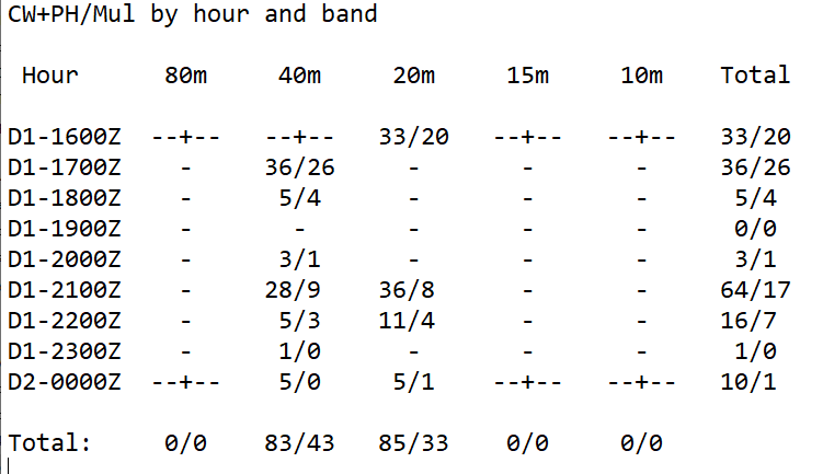
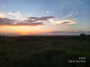 Sunset Sunday evening looking back from CALO over the sound  The w4kaz M/S qso breakdown
By w4kaz, created on 2023.07.02 at 23:31:36 | last changed on 2023.07.06 at 12:13:30 |
Crazy weather. Check
Unique Location. Check.
Mediocre Antennas. CHECK!
No 10m. Check….. 🙁
Typical Field Day.   Check.
see the select photos…..W4KAZ 1B NC 2023 FD photo slide show
Crazy Weather
The days leading up to field day 2023 were filled with rain and prognostications of more to come. While having doubts there would be any chances at having a good chance of operating with the expected lightning, the reservations for the great location had been laid in and paid for. Tropical conditions could have made the trip dicey, but that junk kept on its westerly track to western Carrib.  All of the NC wx junk was spawned by a low pressure system sitting in TN and throwing moisture at us from FL and the gulf coast.  The “bands” of storms flowing through NC peaked midweek, right through travel to the Island.   bleh. Arriving Thursday the wx relented long enough to move vehicle contents indoors. Bands of rain, batches of sunshine alternated ad. infinitum. Lots of time for relaxation. Friday afternoon brought a longer window of almost 3 hours of clear wx for setting up antennas. Then more lightning and rain.
Unique Location
Cape Lookout national park provided a great spot for running a field day operation. The park is a barrier island on the NC coast. Beautiful in its own deserted island sort of way. The wx improved constantly during the four day stay….with the exception of a squall line that that moved slowly through Saturday evening. Operation was shut down for that period, but there was only rain. Great time to catch up on some sleep though.Â
Mediocre Antennas
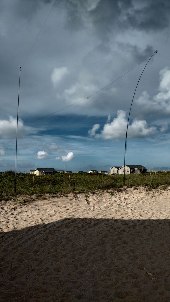
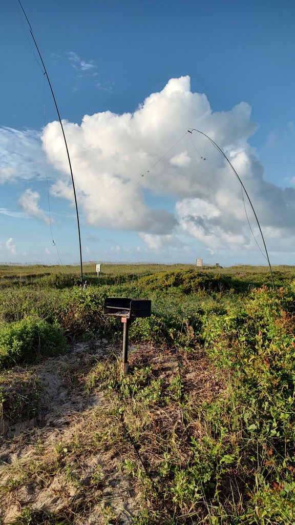
The antenna plan was hampered a bit by having only four of the five masts intended. Something always gets forgotten. Two 40m EFHW antennas were deployed. Both were configured as inverted L’s. The “main” antenna deployed with the horizontal tip pointed North, the second deployed with its tip facing west. The “main” antenna was also manually switchable to being used as an 80m vertical with a K2AV style counterpoise.  The only band that felt loud was 80m. These efhw’s mounted as inv-l’s are a bit compromised on 40m & 20m, both by the configuration and being relatively close to the ground.
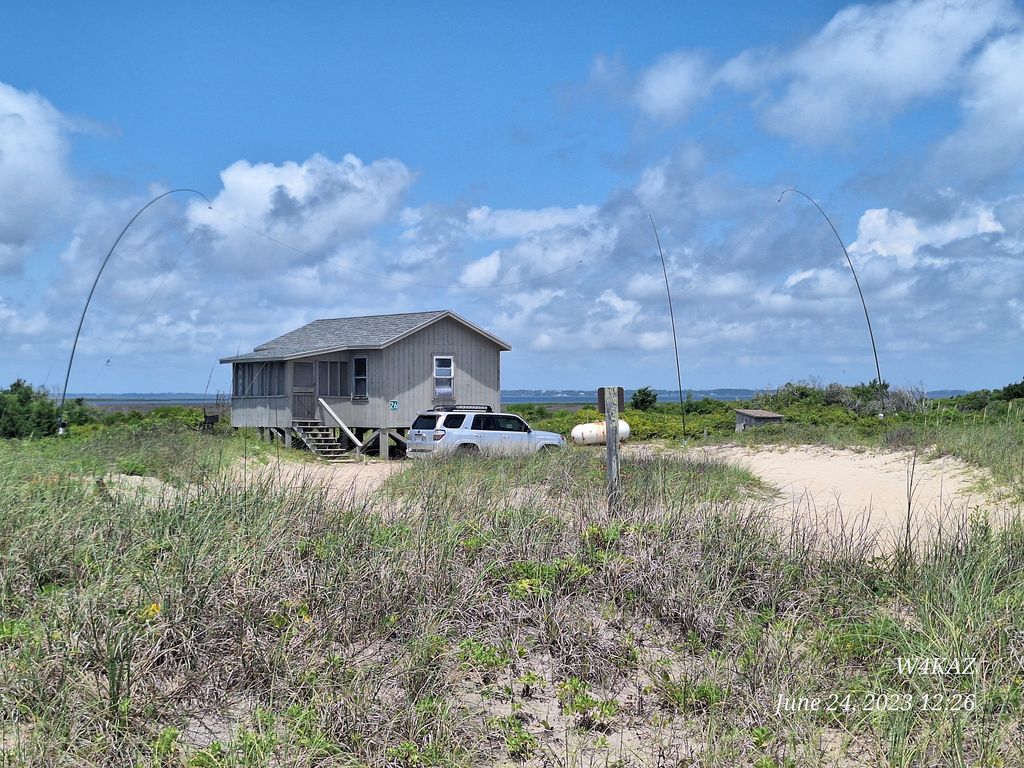
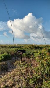
 W4KAZ 1B NC, Cape Lookout qth for the FD weekend, All set for FD. The antennas: Left most and center mast hold “main” 40m EFHW/80m base on left and end at center mast. The rightmost mast holds west facing 40m EFHW which slopes toward ground, and is tied off behind cabin. No 10m
10m was yet again a disappointment. The recent rise in sunspots must be less effective in light of the pole shift and weakening magnetic fields. Radio propagation is probably just a symptom of what might be a much bigger issue. Keeping the band map loaded with packet spots from VA and NC skimmers showed very few spots on 10m at any time I was on the air. 15m was only very slightly better. Perhaps Saturday evening was better.  20m and 40m were the places to be for the most part. 20m was more interesting, and accounted for the bulk of the Qsos logged. The early morning Sunday accounted for the only qsos there, all logged around 0900-1000z.
FD as IOTA Prep
FD antenna choices were made as a test for the upcoming IOTA. The alternate choice was to mount the “main” N/S efhw as described before, but to use a 50m/20m trap dipole as the secondary antenna. This second pair will probably be better for an IOTA situation, with the dipole being a better choice for DX. Alternates/backup antennas are a linked dipole that could be used on any of the individual bands and a set of wire verticals. Also a 15m/10m trap dipole…..just in case.
The Good, the Bad and the Ugly
Start with the ugly…..a slow band of squall lines moved in Saturday evening. Fearing more lightning I dropped all the antennas. Being exhausted, I hit the sack to the pitter-patter of another batch of rain, which turned out to be the last of the trip.  The bad…..missed out on the evening which probably cost a lot of qsos. But without the much needed sleep, Sunday would have been a tough slog. 10m and 15m were disappointing. Missed packing one of the bags with some of the kitchen odds-n-ends, so had to improvise. The good…..Morning coffee….two magnificent sunsets on Friday and Sunday. Cigars and whiskey. Moderate temperatures and a nice breeze. Moderate bug levels.
Details Details Details
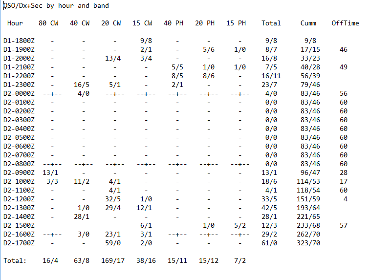
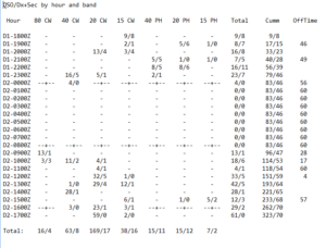 W4KAZ 1B NC 2023 FD breakdown by hour. Saturday afternoon was S&P combined with wishful thinking about 10m and 15m. Didn’t feel loud enough to run on SSB. Then clouds stacking to the west and a check on the wx radar convinced me to lower antennas prematurely. The squall line was slow, and arrived with more rain. Was exhausted anyway so ditched for the evening. Up at 0800Z and started on 80m to try to capture the available qsos. Took a breakfast break at the not so spectacular sunrise, then alternated between 20m/40m/15m for the rest of the morning. Finished up on 20m with the best single hour. Then a couple of hours of breakdown and packing. Bada bing bada boom. Another FD bites the dust. 320-ish qsos, about
By w4kaz, created on 2022.07.12 at 23:08:10 | last changed on 2023.07.06 at 12:04:47 | Schedule is set for another adventure to Cape Lookout, NC over the IOTA weekend. The plan for operation is going to be a very relaxed approach, depending on the WX and radio conditions. Activity will be condensed to mostly Saturday, but maybe some POTA calls Friday night or Sunday morning. Probably will have only 40/20/15/10, and forego 80m. Probably not worth the effort to add 80m if 20m stays open into the evening as it did for FD.
UPDATE, 2022/08/29.
End of July WX made the event mostly a bust. Decent WX on Friday afternoon on arrival, so antenna set-up went swiftly. The weather deteriorated as evening came on, so the Antenna supports were lowered. Saturday morning brought clouds and lightning. The weather attempted to clear of for a couple of short windows. The final window was in the mid afternoon, just as radio conditions began to show promise. Lightning soon returned along with a couple of driving rainstorms early Saturday evening.
The QSO total never grew to useful levels, and the na-067 mult was scarce from the w4kaz op. 37 QSOs total, all on SSB.
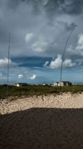
 Photo of antenna mast in down position
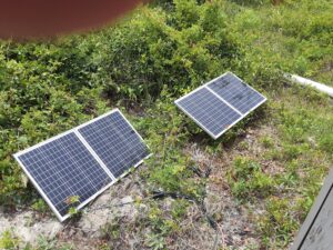 Photo of solar panels for topping off battery.
 The 2022 IOTA station. Destined to be under-utilized
 Antenna is 40m/20m trap dipole. Intermittent lightning in background not depicted.
 Photo of sunset from the day before operating event. Was hoping for this on event day, but no such luck.
By w4kaz, created on 2022.07.12 at 22:29:01 | last changed on 2022.08.29 at 21:10:49 | Passed up a chance to operate at the Korn Krib Kontest Klub of N4GU for a pre-planned solo camp out. Hit my favorite campsite again at Carolina Beach State Park. I allowed for an optional POTA run at Fort Fischer, but lazy won out over ambition on that one. Also used the chance to try out a new camping scheme with mixed success.
I landed on the campsite Thursday afternoon, but made a side trip to Kure Beach, then settled in for the evening. Friday morning was used up sleeping late, making gas run, ice run, and brunch run.
The Antenna Adventure
Setting up the station, a K2, went quick enough. The two antennas went up easily using the same masts I had used to test them with at home. An EFHW for 40m/20m and a 10m/15m trap dipole. FAST……as in too fast.  For some strange reason the EFHW is not tuning………hmmmmmmm. MAYBE omitting the chokes at the feedpoint are the problem. duh-OH!
The antenna still required a bit of tweaking.  “Strange…it worked just fine at home…?” I did waste about 75 minutes screwing around before figuring out the chokes were not installed. After that mistake was resolved I tested out the 80m “variation” that uses the EFHW vertical as a qtr wave on 80m. That is set up as a separate feed point that attaches to the EFHW via a jumper and a swap of coax. With the EFHW working, the 80m variation was actually as trivial as it should have been.
Since band switching 80/40/20 required several manual adjustments, I made a cheat sheet/check list for the tired-and-groggy hours.
Field Day Summary
The weather overnight had been cool(for late June at NC coast), and I woke up feeling hopeful. Never caught any decent propagation on either 10m or 15m, having ZERO qsos on 10m and only 26 on 15m. 80m was so slow I chose going to bed rather than stick it out. With 20m staying open, the stronger stations stayed there longer. Getting viable runs was difficult, outside of a good stretch on 40m abt 6pm, and a decent run Sunday late in the event.
The Dirty Truth
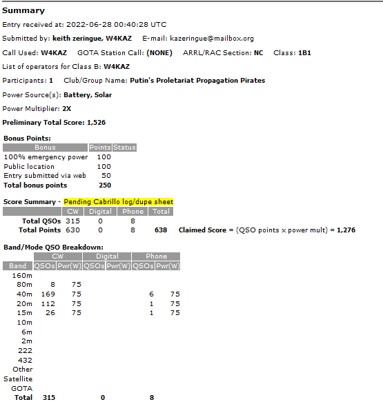 2022 FD w4kaz 1B nc score The Setup and Station
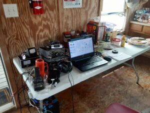
I ran the Elecraft K2 this year at 75 watts, expecting to put in more operating time overnight than during daylight and wanting to stretch the battery. At some point I decided to power the radio from the main battery, and use a smaller backup battery for computer peripherals. This seemed to cause no problems, and helped keep the voltage up on the radio. In direct sun the solar panels provided about 9-10 amps continuous to an MPPT charger. The panels only got direct sun for about 3 hours though and were only providing 4 amps or less for most of the daytime. The battery finished up at about 75%, so the solar assist helped.
 The base station setup for 2022 FD w/W4KAZ Saturday
WX Saturday was fabulous for late June at Kure Beach, NC. Cool breeze picked up right about 1800Z. Conditions seemed mixed, and activity seemed down. Not enough persistence in getting a run going despite seeing decent spot numbers on RBN. Operating was a lot of S&P and band hopping. 20m was open late and 80m action never seemed to pick up in the early evening. Eventually pulled plug for the evening before midnight.
I decided to operate mostly CW to keep the noise down in the campground. Not needed during daylight, but decided to respect quiet hours in park. That plan was almost blown up by forgetting headphones. So I used a pair of earbuds that usually ride shotgun with the computer. I had a second set of buds, but audio was too low a level in those. Could have made an emergency run to a local wally-mart, but decided to make do.
Sunday
Got on the air again at 1000Z, and had one of my more consistent runs on 40m as the daytime crowd got back on the air. Took a break after a couple of hours to scarf a hasty breakfast, then some more butt-on-bench. The shack was a screen tent that was in full sun for the hours of 1530 to about 1700, so the battery fan helped a lot then. Sunday WX was also good, but slightly warmer than Saturday. The only decent 20m run spanned about 50 minutes during the last hours of the event.
 Photo of screen tent shack and additional shade. The shack was back into full shade by the end of the event. After a short break for a late lunch, the station was torn down and packed into a single tote, with some notes taken on items missing/needed. Everything to be re-used for IOTA again at end of July. Copies of log files made. Then a leisurely dis-assembly of antennas and parts of camp. I kept the screen tent up for packing on Monday morning.
 The far side of camp – solar panels, base of 40m EFHW, and gear storage. Note stump, the gremlins got the tree that previously shaded this site over noon hours. Success!
No major problems, injuries, issues. Great weather, plenty of sleep, lots of cigar time, and a chance to relax. Always learn something, and this time learned a pack list is never good enough to catch everything. And even with everything packed, finding it when needed is a problem. Still hunting a set of earbuds that went MIA.
Notes: Compass, headphones/mic spares, !5v usb batt packs!, USB adapters. vehicle storage organizer. Always double check assembly of complex system when rushing. KAT100 troubleshooting required.
|
|