see: Experimenting With Trap Dipoles – Part 1
Those coil and cap experiments described in part #1 eventually led me to the ‘best’ compromise solution for my situation. In the end I chose to build traps that were resonant below the higher band. I also chose to use cap values on the smaller end of the capacitance value range.
-
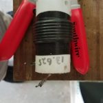
- Sample of original 20m trap using 7 turn coil. This trap experienced SWR shifts under xmit at 100w in CW contest.
-
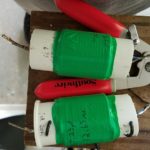
- Revised traps for 20m/40m dipole. The traps use three of the TDK capacitors in series for a total value of 23pf. The 14 turn coil used resonate the traps at 12.65Mhz. Inductance calculated as approx 7uh.
-
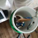
- Revised trap for 20m/40m dipole. The trap use three of the 2KV TDK capacitors in series for a total value of 23pf. The caps are mounted in series on a small bit of PCB for a cap value of 23pf. Joints were soldered slightly long with a bit of excess solder in the hopes of a bit of extra heat sinking.
Sadly the Panasonic capacitors are no longer available. Possible TDK replacement are being tested. These TDK caps are physically smaller, and only 2Kv rated. I intend to use these in series/parallel groups once I determine the best values to stockpile. (TIP#x: leaning to several caps in series to extend the voltage rating) (TIP#x: Also decided to mount the caps in slivers of PCB, and use generous solder on the pads as well as not clipping the leads short, all in a hope to have that function as heat sinking).
Antenna Experiments: In testing, these capacitors worked well on xmit for the first 20m/40m trap dipole, but I ran into problems with a 10m/15m trap. Using 33pf with an inductor of about .92uH I had failure of the capacitors while testing the antenna.
As an alternative on 10m I used a bit larger inductance and a piece of rg8x coax as the tuning capacitor(low value approx 8-9pf). No final verdict on this solution yet, but the antenna functioned for light usage in 2019 WPX cw contest. Antennas will be used at 100w levels, so these cap variations should also prove suitable for this project. If weight is not an issue, gimmick caps from coax are viable choices, though I’d not use them with the traps resonant close to the operating frequency.
Alternatively the 20m/40m dipole has now been used in two different contests with success. A second 20m/40m dipole was constructed, using smaller coils and increased capacitance. This second experiment was less stable than the first, with the 20m SWR increasing slowly. Presumably the capacitors were heating and having the same problems as the 15m/10m model.
What Did NOT Work: In the end, the experiments using larger values of capacitance proved to be poor choices for practical reasons. In the case of 10m, the caps failed outright. In the 20m case, the caps showed instability in the form of rising SWR, likely because they were heating. A revised 20m dipole with traps using a larger coil and smaller values of capacitance proved to be stable. Tip#1….Marginal caps can maybe stand the abuse in a trap if the coil is larger.
At this time I also chose to move the resonant frequency of traps a bit farther away(lower) from the operating frequency on new construction. This resulted in :
- the dipole legs being shortened,
- the impedance on 20m seemed more stable,
- The bandwidth on the lower band(40m) was decreased
- Precision in component selection becomes less critical
That set of compromises suit me, as the capacitance values are readily available, and the overall antenna length is reduced slightly, without any serious performance compromises as compared to an ordinary single band inverted V. The antennas will be tuned to favor the CW segments, and if needed I will use the radio internal antenna tuner(at the home station) to find a match for SSB if required for 40m. The tuner would likely only be required at the upper band edge if at all.
What worked well enough – Final Versions Constructed: RBN testing of the trap dipole versus a normal 20m dipole showed enough uniformity in results that I am not concerned with trap losses. The end result was a set of dipoles both for permanent use at home and several variations made as light weight as possible for portable operating. The final 20m/40m dipole for the home station was constructed with the traps resonant at 12.650Mhz. A coil with 14 turns close wound on the 1.5″ form was used with a capacitor constructed of several ceramics in series giving a value of 23pf.
A 40m/80m antenna was also constructed. These traps used a coil of 12 turns on the 1.5″ form and capacitors in series parallel for a value of 100pf. Resonant frequency was 6.65Mhz. For future construction this design will likely be modified to move the trap resonant frequency down to the 6Mhz range by increasing the number of turns on the coils while using the same 100pf capacitance value.
A practical benefit of having the resonant frequency away from the operating frequency is that component selection becomes less critical. By selecting a resonant point below the band rather than on or near the band, it is not required to have values to resonate at an exact frequency. Instead, it is only required that each trap resonates at close to the same frequency. This is easier to tweak by adjusting the coil, and it becomes fairly simple to have traps that can be adjusted to within 100hz of one another. The caveat here is that the dipole legs are different based on the trap frequency – but these need to be trimmed to length anyway. [It is possible to easily replicate antennas if the traps are easy to replicate. ] So for a 20m/40m dipole, it makes little difference whether the trap is resonant at 12.5Mhz, 12Mhz, or 13Mhz, so long as the antenna legs are trimmed properly for each.
My experiments show that having the capacitive reactance at the higher operating frequency be in the order of 400-750 ohms seems to reduce the current flow through the caps. Probably this is enough to allow otherwise marginal caps to survive without heating and/or exhibiting SWR variations on xmit. The voltage rating needs to be sufficient, and this can be aided by using several caps in series. The caps in use here are all 2kv or 3kv, and used in series to increase voltage ratings. This is sufficient for 100w levels, but unlikely to survive at 1kw or 1.5kw. I have also mounted them on bits of circuit board to keep the leads short and provide a tiny bit of additional heat sinking. Again, good enough for 100w, but QRO – probably not.
Leave a Reply