By w4kaz, created on 2024.03.18 at 12:52:01 | last changed on 2024.03.18 at 13:37:30 |
A really cool RBN mapping site:
Check out the work of HA8TKS. Good format, centers an azimuthal projection on the searched call sign with lots of options. Lots of options to play with, can be used to list the spotter station or see stations that are spotting a caller.
Note 4, RX Antenna: The skimmer system is now using the 3.8 wave inverted L as its RX antenna full time. The only anticipated interruptions will be occasional 160m contests.
2018-08-22:
Note 1: Skimmer station outage in mid July 2018, cause appears to be rx antenna related.
Note 2, Transformer: N6TV identified a mini circuits 14:1 transformer that is suitable for use with the Red Pitaya on RX. Expect the transformer to be available from Red Pitaya, or occasionally N6TV. Available from mini-circuits vendors, but may be expensive in quantity 1.
Note 3, RX antenna: Some what by accident I discovered that the 160m L I use for transmit seems to make a fine all-band rx antenna for the Red Pitaya skimmer set up. FWIW, the antenna is about 140 feet of wire. About 60-70 feet vertical, with the remainder making a dog-leg turn from top of vertical section. From there it runs horizontally NW to second support about 40 feet away, and a second sharper turn to the east, horizontally and slightly downward for the remainder which runs west to east. The radial system is the K2AV type folded counterpoise system described in more detail at link.
N6TV useful links to all the required software files and extras, with proper credit to all the developers and enthusiasts who made it possible for simple folks like us to replace our failed QS1Rs with a Red Pitaya or two:
By w4kaz, created on 2016.10.28 at 21:37:30 | last changed on 2021.10.24 at 13:37:45 |
Update 2021-10-24. Additional info on setup by Bjorn, SM7IUN.  Bjorn describes set up for running a second skimmer thread, but the forked Red Pitaya output can also be used to run a skimmer thread and an SDR with some experimentation. see: https://sm7iun.se/redpitaya/cwskimmer/
[Updated 2016-12-23, see text on Compatibility issue]
Recently discovered an interesting,  affordable,  and relatively new product called Red Pitaya, designed as an open source based piece of test equipment. As a piece of test equipment the Red Pitaya has basic oscilloscope, spectrum analyzer, and signal generator apps available. The apps are designed to run as web applications with Red Pitaya board running a custom Linux and acting as a web server.  Currently the apps are quite basic, but useful despite their simplicity.
With the SDR apps, Pavel has taken this little Red Pitaya board into the areas of interest to many ham ops. The SDR receiver app has the ability to function with several currently available SDR programs. The ability to support feeding six channels into CW skimmer server is of particular interest. There are also transceiver apps which are being used by experimenters to build Red Pitaya based transceivers.
Red Pitaya
The Red Pitaya itself is a board that runs a customized linux OS(their term is ‘ecosystem’) off of an SD memory card. The board has two RF inputs and two RF outputs for use as the heart of a test system. 5V USB power supply input requires 2A. The board has a heat sink on the CPU but a small fan helps cooling. It can connect via ethernet to the network or via a wireless connection. The OS and apps are downloaded from the Red Pitaya website.  SDR apps are available from both the Red Pitaya site and directly from Pavel Demin’s website.  This little SDR kludge is a viable substitute for the Softrock skimmer system previously being run @W4KAZ.
SDR Uses and v0.96 Compatibility Issue
A couple of issues turned out to be a mix of hardware and software problems. The largest problem was a software incompatibility issue between the [then]latest OS v0.96 and the SDR software. This caused problems in the SDR with interference that looks like intermod artifacts. Too much time was spent here looking for hardware problems before stumbling across the documentation on the issue. The solution was simple. It simply required building an SD card with the previous OS version v0.95, and  then configuring(secure password) then re-installing the SDR app.
A couple of the SDR apps available on Pavel’s site originally included an OS that did not allow a persistent password change. To avoid that security vulnerability, the original SD card here was built with v0.96 of the OS. As of October 2016, do NOT try to use v0.96 OS with the SDR apps. V0.95 works with the SDR. Better to have several SD cards with different OS versions should you need a more recent OS for new apps as they are developed.  [Update 2016-12-23.  Per comment from Pave Demin, the SDR applications have been updated and should now work with v0.96 and v0.97 of the Red Pitaya ecosystem.  Not yet migrated to the updates here in the W4KAZ SDR setup.]
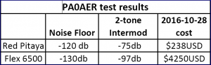
There is not a tremendous amount of information available, as folks are just beginning to explore the possibilities. PA0AER has an interesting post, with a few findings of his summarized in this table.
Yeah, -120db floor and 75 db of intermod suppression should work just fine in a CW skimmer application. Â
Keep in mind, the softrock system being replaced has about 45db of useful dynamic range as implemented here. Plus we get the bonus of using Red Pitaya as a minimal spectrum analyzer and oscilloscope. Maybe even a VNA app.
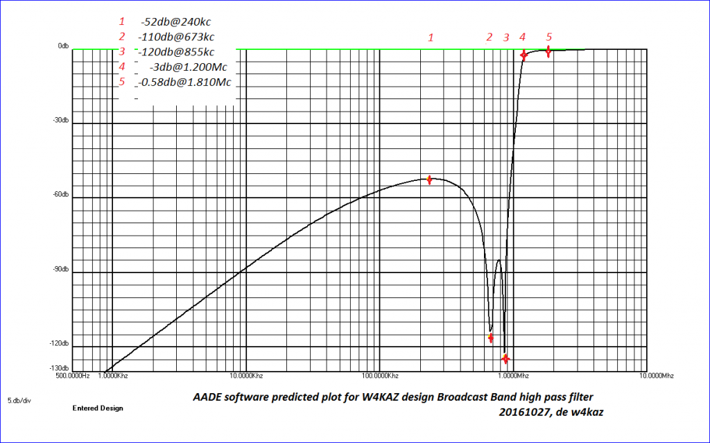
The time spent here going in circles chasing my non existent hardware issues was not a waste. The power supply was cleaned up with better filtering.  Very nice.  Using the AADE filter design program we also came up with a simple-to-build design for a high pass BCB filter.  This filter optimizes the nulls at 680am and 850am, and attenuation drops off rapidly above 1Mc the broadcast band.
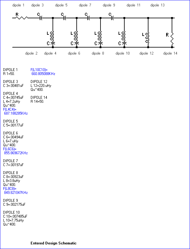
This BCB filter exhibits low loss on 160m, with the modeled 3db cut off frequency being at about 1.2mhz.  Ordinary C0G/NP0 capacitors are used in its construction, having had acceptable results with that type with the W3LPL design receive only band pass filters.  The result was good with testing on the base station.  The difficult part was finding good leaded C0G/NP0 capacitors in proper values to use for construction. Through hole components are becoming rare.  NOTE: Be aware – As designed this filter is a short circuit at DC via the inductor at “dipole 12”.
AADE predicted performance plot of the w4kaz BCB filter from DC to 10Mc. Note the nulls on 680 and 850.
W4KAZ version of BCB filter. Built using NP0/C0G leaded capacitors, t-80-2 torroids, and a 220uh choke.
The plot projected by the AADE filter design program above is a best-case prediction. Â WPTF, 50kw at 680 and WPTK, 10kw at 850 have transmitters about 3 kilometers and 12 kilometers respectively. Â They produced all sorts of intermod in the softrock system. Â The BCB design here is tailored to place the largest nulls where they might do the most work in the KAZshack. Â Getting the 3db cutoff at 1.2Mc was just to try to keep the losses as low as possible on 160m. Â To get an idea of its performance, I plugged it into the station and took S-meter readings on the Kenwood TS-590s. Â The BCB filter dropped WPTF at 680 from pinning the S-meter down to just another strong S9+ signal, not even 10 over S9.
S meter comparisons on the TS-590s using the W4KAZ BCB filter and built in attenuator
Skimming with Red Pitaya SDR
With the software issues corrected, let the CW skimming begin. Â Skimming tests seem to have spot signal levels from Red Pitaya SDR slightly better than those from the Softrock skimmer system. Â Full system stress test coming during 2016 SS CW. Â The Red Pitaya also seems to be very frequency stable, something that was a minor issue with the softrocks. Â When running PowerSDR, comparing Red Pitaya by ear shows it to be a bit less sensitive than the main station rig, a Kenwood ts-590s.
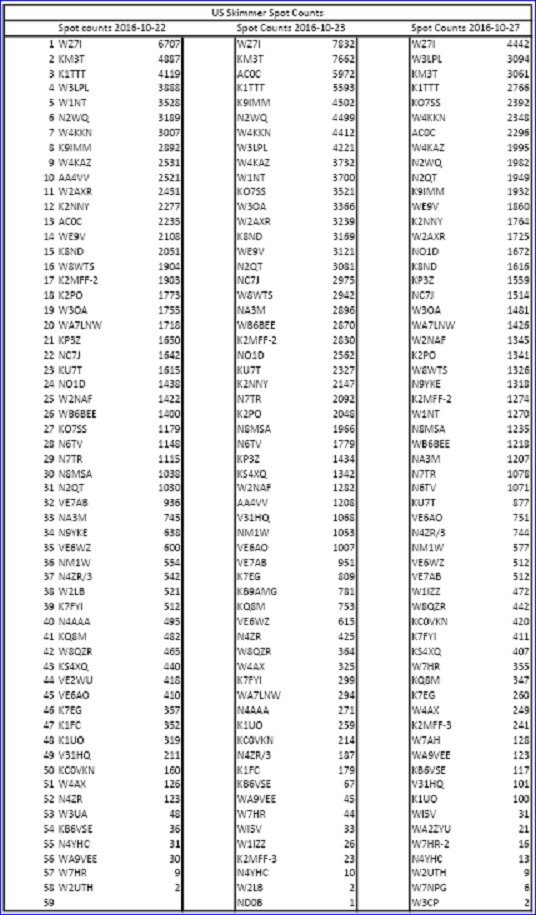
Does it work?
Random selected North American spot counts from days with W4KAZ skimmer station under Red Pitaya
System Reconstruction – Permanent New CW Skimmer
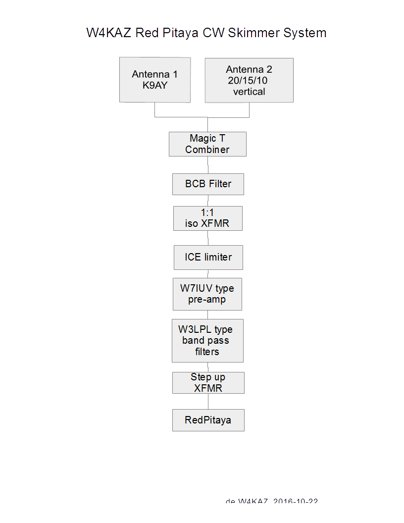
After a good shakedown voyage through Sweepstakes CW, it will be a good time to re-arrange the test Red Pitaya SDR system into a more permanent and compact single system. Â Â One of the dead softrock CPU’s will donate a nice clam shell computer case, and all of the components should fit easily. Â The plan is to wall mount the completed system near the shack cable entrance. Â The softrock system will be raided for its discrete components, the W3LPL style band pass filters as well as the W7IUV pre amps. Â New splitters will be built for the new system to allow for antenna options to change in the future.
Unexplored are some more experimenting to find a proper matching transformer and  Red Pitaya input jumper combinations for the best results.  Some research into the transceiver experimenter comments indicate using a step up transformer is best.  Some have also made mods to the front end that are supposed to boost the sensitivity by lowering the noise floor significantly, from 9 to 12 db.  Currently using a 3:1 cascaded into a 4:1 transformer as step up, with the input attenuation pads bypassed via jumpering on input#1.
Block diagram of likely W4KAZ Red Pitaya SDR CW skimmer system
Important Notation[see update]:
If you choose to experiment with Red Pitaya and the SDR apps,  be sure to create your bootable SD card from a compatible OS.  If you do not, you will be very disappointed at the 25db BDR and the interference and low performance you will experience.  Currently, as of 2016-10-28, the 0.96 ecosystem/OS IS NOT COMPATIBLE with the SDR apps from Pavel Demin.  Either use the ecosystems Pavel has or the last archived version 0.95 from Red Pitaya’s archive.  Do NOT TRY SDR with v0.96 OS!  Been there, done that, have a clean power supply and nice BCB filter to show for it.  [Update 2018-12-23.  Per comment from Pave Demin, the SDR applications have been updated and should now work with v0.96 and v0.97 of the Red Pitaya ecosystem. Migrated to the updates 2017-11-15 here in the W4KAZ SDR setup.]
The Red Pitaya ecosystems come with default root passwords. Suggest resetting your password ASAP.  Also, at least one of the pre-built ecosystems Pavel provides does not allow a persistent root password change.  I suggest using the 0.95 the current ecosystem from Red Pitaya archive and that the root password be reset to something secure if the Red Pitaya is going to be running on your home network.  With the default root password, your network is open/vulnerable to having a hacked linux system behind your router’s firewall.
Other Useful Red Pitaya SDR links circa 2016-10-28:
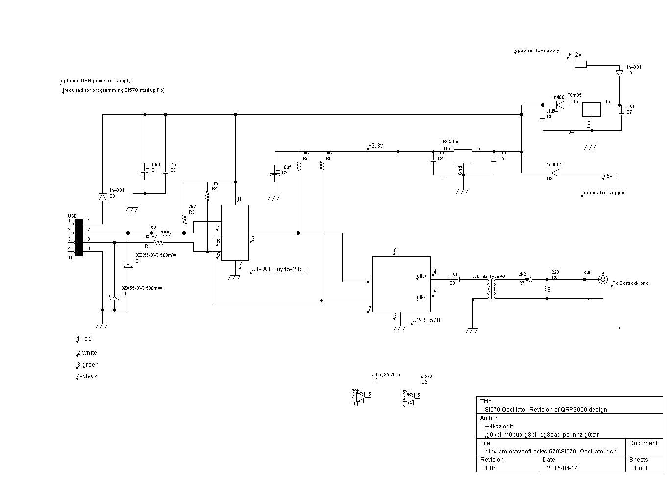
The oscillator itself is pretty simple, and is the bare essential hardware required for re-programming the oscillator for a needed single frequency to use with a Softrock Lite II rx.  It is based on what I saw in the the schematic of the Softrock Ensemble RX, nothing original, just pared down and hijacked from the original Ensemble design.  The Si570 part itself is the bulk of the expense of the oscillator, and the cost of the Si570 chip is almost as much as the Softrock Lite kit itself.   The oscillator signal is fed into the divider through a 10K voltage divider as in the Softrock RX.
So why an Si570 Programmable Oscillator ?
The RX Ensemble kit is a viable alternative expense wise.  It really depends on the intended usage.  Using separate Softrock Lites as single band CW skimmers leads to the choice of a programmable oscillator for customizing the center frequencies, especially for the high bands.  The method used for 20m using the third harmonic seems to result in a decrease in dynamic range.  That results in an increase in false mirror images being reported to RBN by the CW skimmer as actual spots.
Using the Si570, the oscillators can be set at the frequencies needed by the Softrocks, i.e. 4 times the center frequency.  (for 96Khz bandwidth the oscillator would need to be: 20m=56.188, 15m=84.188, and 10m=112.16).  A programmable oscillator also allows switching from 96Khz to 192 Khz bandwidth(20m=56.38,15m=84.38, and 10m=112.38).  Keeping just the bottom half of a 192Khz bandwidth CW skimmer would at a minimum eliminate at least 50% of bad mirror image spots.  There are also likely to be fewer stations CQ’ing below the “.096” section of a band(e.g., most often there is not so much regular CWactivity above 28.096 as there is below).  That is the idea anyway.
The Si570 Programmable Oscillator Prototype:
The first version is deadbugged on a bit of board scrounged from the parts bin. Â Not many parts, but a bit more PCBÂ real estate would have been better. Â Functional rather than esthetic. Â The USB connection is via the usb cable end clipped from an old computer mouse in the parts bin(unlabeled black coil in left of photo). Â Â “Engineer the possible”.
Si570 Programmable Oscillator board for 10m Softrock CW skimmer
Testing the original prototype board pictured resulted in three build mistakes to debug:  a missing 5v connection to the ATTiny and the reversal in polarity on both zener diodes across the USB data pins.  These mistakes prevented function without damage to the components.  After correction of the build errors the software was able to function with the Si570 as needed for both programming the oscillator(‘startup’) frequency and running as a stand-alone oscillator.
The Si570 when programmed for 112.36Mc was found to have an actual oscillation at close to 28.090 exactly from the Softrock divider, as measured with TS-590 and Elecraft K2.  This was with the oscillator inserted in-circuit as the Softrock Lite oscillator via a transformer(5 bifilar turns on a type 43 torroid core) and a 2.2k resistor.  The frequency is very consistent and stable when the power is cycled on/off.
Easy measurement of the actual frequency in place is good enough for initial setting up of the skimmer software. A few KC either way will make little difference in a CW skimmer set-up, as final adjustments were done in CW skimmer software to put the skimmer signals ‘on frequency’.  In this case the CW skimmer center frequency is nearly identical to the Si570 programmed frequency.  That has not been the case with the versions using ordinary crystal oscillators, those having a bit more drift off their nominal value.
A new Softrock Lite II is the 10m test bed, with 15m revision to follow. Â These two bands suffer the most from poor dynamic range and false mirror images. Â The 15m oscillator also has a nasty tendency to drift with temperature changes. Â If the modified softrocks perform as desired it will be time to pair these two bands with the best of the sound cards available. Â That will be a separate game of trial and error. Â The 20m softrock skimmer may also be retrofit, as using the third harmonic for the softrock center frequencies seems to adversely impact the dynamic range.
Photo of 10m Skimmer at W4KAZ
As an aside, the first 10m center frequency chosen was 28.060 into a 192Kc bandwidth sound card. Horrible choice, as it was close enough to the 15m harmonic that interference spikes were present on both bands every 900hz. Â Resetting the Si570 oscillator to place the center Fo for 10m at 28.080 greatly reduced(but not eliminate) the problem. Â Currently set on 28.090 as of 20150414. Â More tinkering required, and migrating the 15m Softrock over to an Si570 oscillator may help.
The current Skimmer package for 20m, 15m and 10m. 20m and 15m will likely be re-worked to use Si570 Programmable Oscillator.
Si570 Programmable Oscillator UPDATE, 2016-11-08
The Si570 oscillator as described was perfectly usable in this application. Â However 10m and 15m performance was was poor on the softrocks, the primary difficulty being a low dynamic range. Â This is indicated by mirror images that appear when SNR values on the actual signals were higher than 35dbSNR.
The most useful work around for this problem is to scan at 192Khz sample rate, and only use the lower half of the sample for the CW skimmer. Â Using the upper 96kc might be easier, as the center frequency could be set at 28.0Mc and 21.0Mc. Â The latter may ulimately be the best approach. Â There are unlikely to be any useful signals below the bottom of the bands, and those could be readily discarded as false or otherwise unusable(i.e., out of band).
LINK LIST, Si570 Programmable Oscillator :
W4KAZ Schematic
Schematic for W4KAZ version of Si570 Programmable Oscillator
W4KAZ BareBones Parts List (PDF) (HTML with links)
By w4kaz, created on 2014.07.03 at 16:50:39 | last changed on 2014.07.03 at 16:57:00 |
File extracts for three summer contests from four skimmer stations for May 2014’s CQ WPX and June’s JARL All Asia and ARRL FD. Â The files are by skimmer spotting station and are sorted in datetime order.
By w4kaz, created on 2013.05.23 at 09:37:03 | last changed on 2014.04.08 at 11:06:23 |
Some repairs to the skimmer station set up have been made after losing the 20m and 10m softrocks. Â Both were probably damaged due to modifications I made to the voltage regulation circuits. Â That appeared to eventually fry the QSD chip, which is the heart of a softrock.
The 20m skimmer was replaced completely with a new softrock lite. Â 10m is pending re-work, but replacement would probably be the best bet.
So for WPX 2013 there are five bands available, 160m through 15m. Â These will be active during WPX intermittently. Â I intend to bring them up and down based upon my own operating. Â The skimmer will be down when I am operating.
Other changes made to the skimmer station include loading windows XP onto the Optiplex 360 that had been running windows vista. Â Vista was able to run one instance of CW skimmer, but was not able to support two instances simultaneously due to sound card conflicts. Â Windows XP does not seem to have a problem with the two sound cards, and is an OS supported by CWSkimmer(Vista is NOT supported by skimmer).
By w4kaz, created on 2013.02.16 at 15:53:19 | last changed on 2013.02.17 at 16:39:59 |
After several contests, monitoring of the softrock skimmers has turned up a bit of a problem with using softrocks as the skimmer platform. Â Very strong signals are producing a mirror image that is often reported as a spot to the RBN. Â Certain to be annoying for the S&P packet crowd during a contest. Â Annoying enough that a few flame mails have arrived.
The volume of the bad spots is relatively low on the lower bands, and more common on the higher bands. Â 40m is somewhere in the middle, with most of the bad spots being sent for domestic USA stations.
The problem is a combination of the hardware and software, both contributing to the problem. Â A software fix could potentially be made to CW skimmer or to the RBN aggregator to correct for the problem. Â Will inquire to the authors…..
In the meantime the best solution available is to throttle the RBN aggregator to allow only spots below the center frequency to be reported. Â For example, the 15m skimmer is based on a softrock with a center frequency at approximately 21044.5Mc. Â So for the duration of the ARRL DX CW contest, an entry in the “Notched Frequencies” will be active to not report 21044.5-21100 to the RBN.
That solution does nothing to correct for half of the possible bad spots(i.e., a strong signal above the center frequency whose mirror image is being spotted below the softrock center frequency). Â But it should alleviate many/most of the actual bad spots, since most run stations prefer to operate as low in the band as they are able.
Open to other suggestions short of replacing the softrocks with better (yet unaffordable) hardware.
Update 20130217, 2140Z: Â There are new versions of both skimmer and aggregator. Â Perhaps upgrade will help.