By w4kaz, created on 2019.11.09 at 15:43:10 | last changed on 2021.05.06 at 22:39:49 |
Many thanks to Guy, K2AV for tips, suggestions, and testing assistance to help resolve the following problems.
An unanticipated problem with fixing broken antenna systems is that it begins to work better. Well – “duh”, right?Â
After making repairs to the antenna switch and the 160m inv-L over the past couple of months, the antenna systems are nearing the end of a minor overhaul. Since about May, the CW Skimmer has been using a K9AY as the main RX antenna. For the period of 2 years prior it has been using the 160m Inv L as the RX antenna, until problems cropped up in May 2019[a broken connection on the feedline at the switch box.]
After correcting the broken connection and re-assembling the skimmer station, K2AV reported having spurs on harmonics when testing on 160m. Upon a closer I found several other stations for which the SDR was also generating harmonic spurs on higher bands for signals of 40-43 DB SNR into the skimmer station SDR.  This was resulting in bad spots to the RBN, and as is sometimes noted “results may be unpredictable”.
All of the spurs appear to be caused by overload mixing from nearby BCB stations on 680, 850, 1360, and 1510. Some of the problem was previously handled with the BCB filter constructed with notches tuned for 680 and 850. Upon re-assemble, the BCB QRM was still sneaking in.
The bulk of the issue has been resolved by bonding the BCB filter enclosure directly to the SDR enclosure. In a belt and suspenders approach, I constructed a second filter that has a higher cut off frequency.  It appears to function as designed, notching 1360, 850, and 680. It adds about 20db attenuation at 1510, and rolls off at about 1650 while applying less than a db attenuation at 1800 to allow 160m into the system. This second filter was placed at the input to the skimmer station preamplifier in the hopes of reducing the interference further.
Currently the result appears promising, as the signal SNR numbers from the skimmer seem to have benefited from the dual filtering scheme. Perhaps the stations at 1360 and 1510 were causing more overload than I originally thought. While neither is as strong as 680 or 850 into this QTH, both are over S-9 on the base radio using the same antenna for RX.
So now the curiosity about BCB filtering has been tweaked, and experiments modeling and building alternate filter choices are continuing.
If you are seeing bad RBN spots originating from the W4KAZ skimmer, please email the info so I can attempt to remediate the problems.
By w4kaz, created on 2019.06.08 at 12:27:11 | last changed on 2021.05.06 at 21:06:51 |
I have been using a telescoping fiberglass mast of one sort or another since 2005 or so. Most folks seem to be using these masts mostly as designed, i.e. relying on the friction fit, or using tape or hose clamps to keep the mast extended under load. None of those seemed ideal for my plans to use them with dipoles(inverted V config).
The first pole I obtained was from Henry, K4TMC (tmastco.com).(FWIW, I am acquainted with Henry via our membership in PVRC. Henry also sold me a very nice Elecraft K2 when he upgraded to the K3, and other assorted sections of surplus mast.)
This is the 32 foot pole, which results in about 29-30 foot of usable length once extended. Relying on friction fit, I ran into a couple of problems I think common to ALL of these similar type masts. The first problem is the amount of friction required to keep the poles from collapsing was also enough to make them difficult to collapse in very hot or very cold weather.(38C/98F or 0C/32F) Tape and hose clamps are usually enough to resolve that, but bring their own issues.
Tape tends to leave a lot of residue at the joint at 38C(i.e., ‘sticky mess’), which is a problem on sandy beaches. Sand does not enhance the experience of using one of these masts when it sticks to the joints. I also did not like the amount of pressure hose clamps required, nor the amount of time needed to install them in correct order(at 98F oceanside), or to fasten them without crushing the fiberglass accidentally. Because of “spontaneous collapsing” under certain types of pressure, the friction fit is not ideal for use with dipoles, my preferred antenna for portable ops.
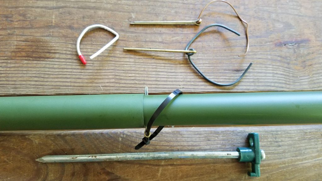
The solution I chose was to drill the mast and use 1/8 or 3/32 cotter pins at the bottom of sections just above where they rest when extended. The pin rests on top of the next lower section, so no problems trying to align holes through two sections. Saving another 1000 words……
A section of mast extended showing position of pin, which goes through only the base of the single section.
Over the past 10 years or so I have acquired a few additional masts. Primarily to have the ability to deploy more than a single antenna, but also as redundant or spare masts. [Two is one, one is none.] These additional masts include the 12m Spiderbeam pole, both a 28 and 32 foot mast from Jackite, a 22 foot mast that was marketed as a flagpole, and several Shakespeare 20 foot Wonderpoles. The Wonderpoles are used mostly to elevate the ends of the dipole legs when it seems appropriate(mostly constricted spaces).
The mast from K4TMC has seen the most use over the last decade. It has a good combination of stiffness and flexibility for its length. I had my doubts about drilling holes for the cotter pins, but the mast has been deployed for extended periods with little signs of anything more than minor cosmetic damage. The Spiderbeam mast seems to be much more flexible, which tends to negate is useful length as a center support for dipoles. Both Jackite masts seem to be the most rigid of the group, but I have used these less than any of the others – they are relatively new buys.
The disappointment of the group for me is the Spiderbeam mast. Its flexibility requires guying to keep it from noodling with the weight of a very light weight 40m dipole made of 18ga wire. Best practice seems to be best to attach the feedline to the mast for any of these type masts, but absolutely essential with the Spiderbeam. My Spiderbeam pole also becomes difficult to extend to its full length the more it bends, although that does help keep it from spontaneous collapse. Also more difficult to deploy in heavy wind at the beach due to flexibility, common to all but more pronounced on the Spiderbeam. The other masts are more self supporting when used with the auger bases. This may indeed have more to do with their overall shorter length, and the spiderbeam masts are indeed intended to be guyed by the manufacturer. I would prefer not to use guys to save time, but in several excursions I was unable to use the full length of the Spiderbeam mast sans guy lines. Even with guys the Spiderbeam pole had excessive droop in high winds oceanside, so the additional time required did not seem worth the effort. Taken all together the Spiderbeam mast was not taking my dipole significantly higher than shorter masts.
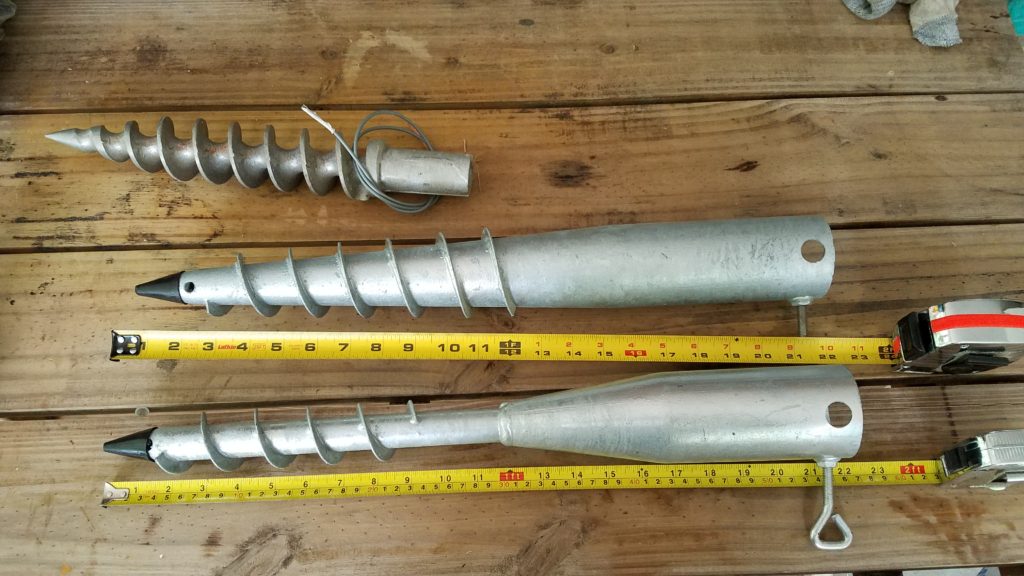
Auger Bases? Why didn’t I think of that? : The other divergence from the norm is my use of these auger bases. These auger bases are items I have scrounged from different sources. The first pair of them I obtained from Harbor Freight in the early 2000’s, where they were being marketed as beach umbrella stands. That source disappeared soon after my purchase. A second group of smaller augers[NOT pictured below] are marketed as “Aussie Augers”, but needed modification to use with the fiberglass masts(unless you don’t mind removing the end caps from the bottom).
These augers pictured below were available via Amazon in the US in 2019. They work extremely well in sand. They are heavier gauge material than the Harbor Freight versions. The larger tapered base is my first choice for sand and seems to be the strongest. It would also work anywhere with a deep layer of loam or sandy topsoil. The base with the narrow welded on auger is more useful where the soil is less friendly, with stone or tree roots. I use the narrow base in my home yard, which is chock full of quartz stones and tree roots. It sometimes requires multiple placement attempts, but seldom takes more than a few minutes to install. For areas with no topsoil, shallow stone, or mountains, this solution might be less than ideal. The other caveat is leaving a hole in the deployment area.
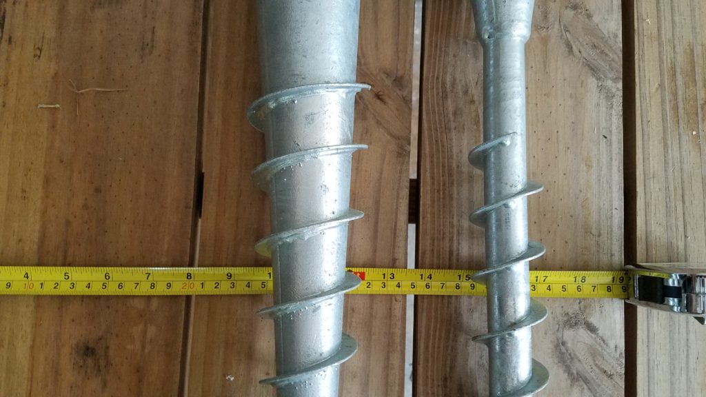
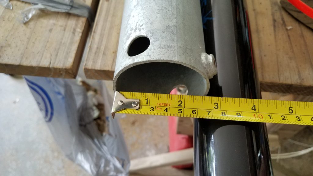
Both bases are about 60cm in length(22 inches) and have a 60-61mm throat width(approx 2-3/8 inches). This is just barely wide enough for the Spiderbeam mast to fit without removing the base cap. All of the other masts are a bit smaller at the base and fit in easily. The large base has a depth about 178mm(7 inches) and the larger a depth of 127mm(5 inches). FWIW, with the smaller diameter masts I often insert a section of 2″ PVC into the base as a bushing sleeve, and the mast into the PVC bushing section. Large tapered base at Amazon [American Ground Screw Model 2] Narrow welded base at Amazon [American Ground Screw Model 1 with Cap ]
Two different types of auger bases for use with telescoping masts by W4KAZ
Two different types of auger bases primary difference is size. The auger on the left has threads down a tapered shaft. On the right, the auger shaft is a uniform width of tube welded onto the top section. The usable depth on the left auger is also about 2 inches more than the one of the right.
I don’t expect I have been the first to go down this less traveled path but have not seen it documented elsewhere. So some photos above for reference. I drilled 9/64 holes in the bottom of each nested section, just ABOVE the joints, and use 1/8 cotter pins.
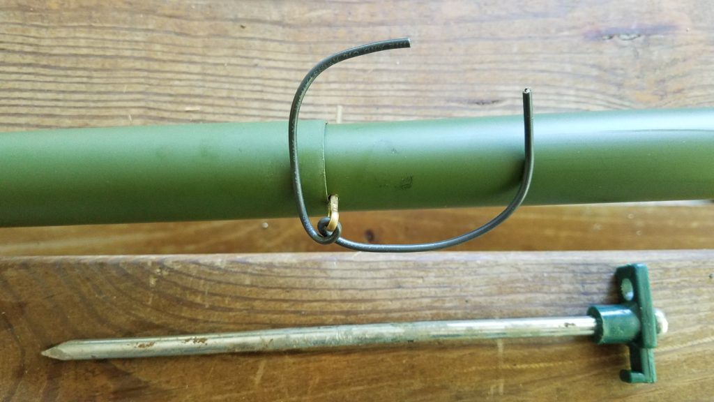
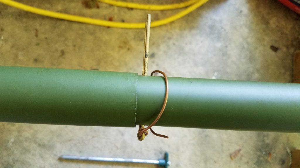
My 10+ year old mast from K4TMC has been deployed numerous times. There is still only minor wear to the drilled holes, and zero cracking or vertical splits. YMMV. Caveat Emptor. An additional tip would be to have spare pins, and pins in at least two lengths. The bits of wire are used to keep the pins from vibrating loose in the ocean breeze. The also are used with coax to keep the feedline close to the mast. Generally I tape the feedline when using twinlead.
The choice of feedline is made on deployment depending on the distance from the antenna to the operating position. I use LMR240/RFC240 for the feedline drops when the operating position is close to the antenna, and 300 ohm ladderline from DX engineering for long runs.
N6TV useful links to all the required software files and extras, with proper credit to all the developers and enthusiasts who made it possible for simple folks like us to replace our failed QS1Rs with a Red Pitaya or two:
By w4kaz, created on 2012.09.06 at 11:57:20 | last changed on 2021.05.06 at 21:07:45 |
Yesterday, having not yet thought of a better way to do a meaningful real-world test on the sound card with what is available in the KazShack, I fired up the 80m softrock on the ASUS Xonar DX for a bit of putzing around.
Test condx:
Transmitting a cw signal(a string of dashes at about 18wpm) at 5w into a dummy load on separate radio, noting the SNR readings obtained by CW skimmer from the SoftRock center frequency(353395x) to its upper limit. With the xonar DX set to 192khz scan rate, the actual upper limit on the readings was 3629.60. SoftRock connected to normal antenna system, a NE facing K9AY with W7IUV pre-amp. In summary, a sound card test using the SoftRock system as input source.
fq….—-SNR(dB) 3534.5—-42
3543-3593-42-40
3603——37 3613——35 3623——32 3629.6—-36
After CW skimmer collected a bit of data, the SNR readings above 3600 improved to 37-39.
So the worst case for CW skimmer(as currently configured) using a Xonar DX is being 6db less sensitive at the upper edge of the 192khz bandwidth than it is at the center. That is actually a lot better than I expected for an audio device pressed into service outside normal audio ranges (and I already liked the Xonar DX).
My curiosity is now nagging me to run the same tests on all of the other in-shack cards more methodically at their maximum scan rates(mostly 96khz), and to find a lower level outside signal source. I’ll try to recruit a fellow in the near field who will better be able to generate a low level test signal.
But with the WX here improving, all of that might not happen for several months. 😉
By w4kaz, created on 2012.07.06 at 10:42:06 | last changed on 2021.05.06 at 21:08:01 |
Created a page of links and several related pages of information on the ongoing construction of the CW Skimmer station at W4KAZ.
Because of the nature of the blog package used for this website, it is easier to save this skimmer related info on ‘pages’ rather than as a “post” because it seems like a project that I’d like to have semi-permanently documented, and have the documentation easily found. Whooop…there it iz….Incomplete, but slowly growing, and probably to be frequently edited in the short term.
By w4kaz, created on 2010.03.03 at 20:54:49 | last changed on 2021.05.06 at 21:12:35 |
Leave it to the RedmondGeeks to create a useful tool but leave it undocumented rather than make it easily available. And a big thanks to NumberOneSon for showing me the trick.
There’s a feature for Windows 7 users called GodMode, which is simply a tool/folder that has a lot of the more useful system administration tasks grouped together in one place. [As opposed to navigating five screens to get to them.]
All that is required to use the feature is to create a folder then re-name it. See the link for the details or just goog up the word “godmode” for yourself. No use re-inventing the wheel here.
By w4kaz, created on 2009.12.21 at 05:17:27 | last changed on 2021.05.06 at 21:13:48 |
Sometimes procrastination pays off. On W7IUV’s web site, he has a link to his “W7IUV preamp”. The document was revised a few months ago, and it includes schematics and parts lists for both versions, as well as a general discussion on the preamp. It appears that no suitable surface mount parts were found to replace the transistor.
Not like I want to play with surface mount components anyway.
note: The Zettler and P&B DPDT relays are interchangeable(pin layout compatible) if the power ratings are sufficient for your application and both poles of the P&B are tied together and used as an SPDT[i.e., for the KK1L 6×2 switch project]
By w4kaz, created on 2009.02.08 at 20:32:44 | last changed on 2021.05.06 at 21:16:43 |
Obtained a third hand Array Soultions SixPak from N4YDU. The control box needed a wee bit of refurb. The LED indicators were not all working, although the switch itself is functioning well. One LED was cracked, three others blown, along with four of the resistors.
So, heating up the soldering iron and pulling a few parts was needed. This was more trouble than expected. The board is very well done, and it is simple to remove from the box. But I didn’t anticipate the minor fly in the ointment. The holes are ‘plated through’. The LED’s were simple enough to replace, and I had close match replacement LEDs in the parts bin. The four bad resistors were a bit less cooperative. It was difficult to remove enough solder with the solder wick.
The new resistors were difficult to install, because the plated through holes were a close fit even when clean. Downright difficult with a coat of solder in them. I resorted to alternately heating the holes and pushing each lead through a couple of millimeters at a time. Once I had enough fed through, I was able to grab the leads with forceps. Then I was able to hold both leads, apply hot iron, and pull the part down flush with the PCB.
So what should have taken 15 minutes tops probably took almost 90 minutes. Grrrr. Not difficult, just frustrating. The LEDs I had on hand are not exact color matches, but very close when lit. The red matches better than the greens, but I didn’t want to chance messing something up – if it ain’t broke don’t fix it. I’ll replace them if they blow up.
The SixPak is probably overkill here, but will be a good thing if a certain SB-1000 ever migrates into the KazShack. It could happen.
Now I just need to figure out the best way to re-configure the station. The idea is to allow SO2R experimentation at some point. That will require some alternate antennas and a set of filters on each. I’m not there yet. Then maybe a W9XT band decoder board for auto band switching.
Coming along, slow but sure. Sure to slow down that is, because the first tuition check for the college bound eldest is due in three months.