By w4kaz, created on 2025.03.15 at 19:27:17 | last changed on 2026.05.04 at 20:52:25 |
Looking at a few of the promo vids folks have posted so far about the Pota33H mast I decided to take a chance on it and the order arrived late last week. On first look I thought it might not be long enough to stretch to the 30-ish feet, but I underestimated the strength of the carbon fiber. For its short length it has a lot of sections inside, and the top section is about 1/2 inch diameter tube. Thicker tubes are stronger than thinner. The carbon fiber provides a lot of strength in a much thinner level of material, so it should be just fine. I expect it will have less flop/droop than any of the fiberglass masts. But the folks who got it made should be happy, it seems to check all of the design goals any backpacker might have for compact, lightweight, and strength.
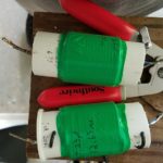
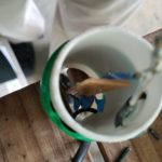
It did have a couple of caveats for my own uses. If the mast were a full 48 inches I would like it better, but it was designed for its short collapsed length. The second caveat is more of an impact for my own purposes. The base piece at the bottom of the mast is heavy duty, and quite thick. The end cap is thick and sturdy. So thick that as delivered it is just slightly too large to fit in one of my favored mount methods, a trailer hitch post holder.
The end cap from the pota33H after filing is about 60mm diameter. It fits into one of the hitch mount post supports, but not the other.
The hitch mount that does not accept the Pota 33 mast appears to also be about 62mm diameter. Perhaps it is out of round? Thicker walls? Will need the micrometer to find out, the two different pole receptacles appear to be the same size to eyeball mark 1.
The hitch mount that accepts the Pota 33 mast is about 62mm diameter.
Pota 33 base fits for this hitch mount after a bit of judicious filing
Pota 33 base is too fat for this hitch mount
The truck hitch receiver with a step extension that supports the telescoping fiberglass mast. The mast du’jour is the Jac-kite 31 footer. Plus assorted extra junk in the truck bed.
After trying the mast in both mounts it was clear it was very close to being able to function in one of them. After a few passes with a file around the widest part of the pota33h’s base cap, it was able to just barely slide in to the hitch mount. That will make deploying portable a bit more convenient. Kinda hate putting the file to a massage brand new sort-of-pricey mast, but WTF. Not like I was sending it back anyway.
Also, the pota33h should be FB for use in the screw in earth anchors I use for the beach side deployments. As long as it works with those its worth trying.
The unknowns now are: What it will do with a real antenna attached? Will the friction fit hold in the wind? Will the friction fit hold an antenna without collapsing in the 20 knot winds common on Cape Lookout? Will the carbon fiber be better than fiberglass when stressed? Will the thin wall carbon fiber tubes crack and split, compared to fiberglass more or less likely? Will sand prove to be a bigger problem for this mast than others? Will it really be less floppy than its fiberglass predecessors? Will sand cause it issues? Will it have difficulty being lowered after a roll in the Cape Lookout sand? TBD…soon!
By w4kaz, created on 2025.01.06 at 10:01:53 | last changed on 2025.01.09 at 16:30:42 |
After a detour to building the 2 band trap dipoles using rg-316 type coax, the worm turned. The failure of a couple of the coax trap antennas due to incomplete sealing and weather proofing the coax became a problem. The antenna at home failed. Two of them. Then the antenna being used for portable ops failed during the 2024 NC QSO party. In the meantime, the home antennas built from coils and capacitors for 40m/20m are still in use 4 years later with no change in resonance points.
Rather than continue with a seemingly fragile system it was time to revert to the coil-and-cap design. Avoiding the cap failures previously experienced on the 10m/15m antenna is addressed by using caps with low enough values to be appropriate for the 10/15 version. So a supply of the TDK ceramic caps was laid in. These caps have 3KV and 6KV ratings. Parts#810-CC45SL3JD080DYGN (example is 8pf SL 6kv) from mouser. TDK Data Sheet for Sl ceramic capacitors.
For the 10m trap a value of 10pf was used, with 16 turns of 18ga stranded wire tightly wound on a 1 inch diameter piece of fiberglass tube. (calculated inductance is about 3.25uh) This originally resonated about 27500, but crept up after taping and sealing to 28000. Decided to roll with them as constructed. These may be fragile, too fragile for portable use, as 18ga wire was also used for the connections. NOTE: USE LARGER GA WIRE FOR CONNECTIONS.
The “tricksey” part discovered previously is that using caps with a large enough reactance on the upper band helps them survive by limiting the current actually flowing through the capacitor. At the 100w levels the voltages are less of an issue than the current handling. Using parallel-series combinations can also help, depending on what value caps are available.
The downside is that the inductance value to resonate the trap for 10m becomes relatively large. This makes tuning the antenna for the 15m band “tricksey”. The 15m tail is short, maybe 15 inches from the relatively large inductance used in the trap. When trimming, very small trimmings move the 15m resonance quite a bit more than on a normal 15m dipole. The good news is that the 10m band is only very slightly effected by trimming wire on the 15m side of the trap. The 15m tails needed to be replaced and re-trimmed after trimming a 2 inch bit of wire moved resonance from 20.85mhz to 21.65mhz. oops. SMALL SNIPS FOR 15m tuning!!!!
After trimming, the 10m/15m antenna is good from 28000 to 28750, and also covers the entire 15m band. STOP….DO NOT TRIM AGAIN!
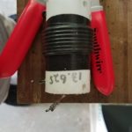
The 20m/40m version is built with a trap resonance at 13.65mhz. The 20m legs are approximately 15ft long. The 40m legs will be about the same. (?actual measurements?) Total antenna length of about 60 feet.
Both of the 2019 home 20m/40m trap dipoles can be easily matched with the Kenwood TS-590 internal tuner for use on 10m as well, which provides options. Worked JA’s on 10m using the 20m/40m trap dipole several times now. The new version for the 20m/40m portable does NOT tune on 10m, probably because of the different value of capacitance/inductance used, or maybe because the new antenna traps resonate at 13.65Mhz instead of 12.5Mhz. The new trapped antenna covers the entire 20m band, with the highest SWR of 1.5:1 at 14000-14015. The 40m band is below 1.5:1 SWR from 7000 to about 7250, with the swr going to about 2.3:1 at 7300.
(For future testing, add turns
Using the new 1 inch o.d.(~25mm) fiberglass form material as the coil form and the TDK capacitors:
Freq———Capacitor——-–# turns calculated——#turns actual——-
27.7Mhz—>10pf————->12 turns (approx)—–> 12 turns, 28Mhz(use 12.5?) (calculated inductance of 3.25uH as constructed)
20.66Mhz–> ?????
13.75Mhz—> 34pf————>16 turns —— ——–> 16.5 turns, 13.65Mhz (calculated inductance 4.04uh)
6.75Mhz—-> 16.33 turns
[edited for links and notes, 2023/07/15] The original trap dipoles were constructed using coils and caps. Using Rg-58 for the coax style trap dipoles was rejected because of the weight and size of rg-58 coax traps. Using RG-58 defeated the primary goal of making the antenna as light weight as possible.
Somewhere I picked up the notion of using rg-174 or rg-316 type mini coax to make the traps. It looks like the voltage ratings on the rg-174 is higher(1100v rms), so that was chosen for the first experiments. If luck holds out, the tiny coax will be sufficient for use on the dipole traps for a full 100w CW. Using the smaller lighter mini coax will allow for lightweight construction from easily available materials that can be easily supported using telescoping fiberglass masts like those available from Spiderbeam, MFJ, or Jackite. i.e., perfect for portable, field day, rover QSO parties, or POTA/SOTA.
The trap calculator program hosted by KC1KCCgave me some starting numbers to work with, and actual trap measurements came out quite close to the calculated values. [alternate calculator at K7MEM]  The traps are built with the coax coils wound reasonably tight to the form, and the coils were taped down with electrical tape prior to taking measurements. These are all wound on small sections of the same sort of plumbing drain tailpieces that are 1.5″ od (38mm od). (e.g., in the US available from Lowes or any hardware store selling plumbing supplies.) The table below are of traps as built and tested with the nanovna.
frequency
turns rg-174
27.7
3.33
20.66
4.33
13.75
6.1
6.75
10.3 [calculated]
Update, 2024-04-04
Received a new 1 inch o.d.(~25mm) form material that is lighter. testing.
Freq———–# turns calculated——#turns actual——- 27.7Mhz—>5 turns (approx)—–> 5 turns, 24.8Mhz(use 4.5?)
20.66Mhz–> 6.25 turns————> 6.25 turns, 19.65Mhz(use 6)
13.75Mhz—> 8.75 turns ——–> 9 turns, 13.5Mhz & 13.7Mhz
6.75Mhz—-> 16.33 turns END 2024-04-04 Update
Test Antennas:
The test antennas were built for the CW segments of each band. With the best SWR centered on the xx.070 area it will probably give enough coverage for both CW and SSB operation without a tuner. An 80m/40m version will require tails for 80m adjustments.
Testing of two antennas was done before the May 2022 CQ WPX CW contest. The 20m/15m version tuned easily….after I figured out I was working on that instead of the 10m antenna. Read those labels, because at least I had them labeled properly when they were built several weeks earlier. The 10m/15m version also tuned easily.
[aside: the 15m/20m trap is now in service as the skimmer station antenna, after a recent storm broke the 160m inv-l]
Although I missed the WPX contest, I soon got a chance to do antenna testing at 100w levels.  Both antennas handled the power easily with no signs of SWR rise. Both were tested at 10 seconds, 30 seconds, 60 seconds and five minutes of CW key-down.
Hoping for good conditions in FD to allow testing of the 10m/15m version. Sunspots, do your thing!
[2023-07-15 additional notes] The coax traps began showing swr problems on 10m after a few months in the weather. Expecting this to be a problem with water intrusion. testing the use of WeldBond glue as a sealant. [alternative….Elmers ProBond] Also testing the adhesive as a sort of q-dope to seal the coils on the form.
Adding a linked in tail to the 20m/30m EFHW turned out to be about as easy as you might expect. The 40m EFHW was tuned for 7.100. The other bands could be easily matched by selecting the best match via moving the transformer tap.Â
The links at 20m and 30m will allow a lot of versatility at the cost of lowering the antenna to connect or disconnect the links. Likewise with the transformer taps. So a bit of footwork is the tradeoff for multi-banding. But its not just the band changes. Judicious configuration choices allow the possibility of multiple choices of radiation patterns.
BAND
TAP
Best SWR
SWR range to expect
40m
8.5:1
7.1(1:1)
Entire band, (1.3–>1.6)
30m(j)
8.5:1
10.25(1.6:1)
Entire band, 1.6:1 with wire drooping
30m(j)
8.5:1
10.1(1.3)
Entire band, 1.3:1 with wire pulled taut
30m(j)
7.5:1
10.3(1.4)
Alternate tap,1.4:1 with wire pulled taut
20m(40m-tail)
6.5:1
14(1.4)
Entire band 1.4–>1.6)
20m(no 30m/40m tails)
8.5:1
14.025(1.4)
Entire band favoring CW section
15m(40m tail)
4.5:1
21(1.1)
Entire band 1.1–>1.8
15m(j)
4.5:1
21.010(1.4)
Entire band under 2:1(wire drooping)
15m(j)
4.5:1
21.010(1.0)
Entire band flat with wire pulled taut
10m(40m tail)
6.5:1
28.0-29
Entire band with tap 3 , 2 or 1
10m
6.5:1
28.000-29.25
28.00 thru 28.800 under 2:1(swr 1.2:1 on CW)
10m
8.5:1
28.00(1.4)
28.00 thru 28.75 < 2:1(swr 1.4:1 on CW)
*note1: “40m tail” implies both 40m and 30m links are attached, other settings are for the 20m/10m as 20m efhw or 30m/15m as 30m efhw.
note2: The transformer taps are numbered 1-5, where tap 1=4.5:1, 2=5.5:1, 3=6.5:1, 4=7.5:1, and tap 5=8.5:1 turns ratios. corresponding impedance values would be 1013, 1513, 2113, 2813, and 3613 ohms.
note3: -right click and “view image” to see full size images below
Model Radiation patterns-10m
For the 10m images above, on the left is the modeled current and radiation patterns for the 40m EFHW when used on 10m. The right is the current and radiation pattern for the 20m EFHW used on 10m. Switching requires lowering the antenna to either detach or reattach the link at 20m.
Given the lengths of the wire using a 30 foot(~9 meter) support, either configuration will have a considerable vertical component. The 40m version will add a substantial horizontal component. The vertical components will mimic the horizontal patterns to some extent. But the patterns will likely favor different directions. The differences will surely be modest – maybe enough to be worth testing as options. If nothing else, it may help reduce QRN in some circumstances.
Radiation patterns-20m
For 20m, the radiation patterns might actually be more interesting. The full wave version(from 40m configuration) will present a compressed combination of horizontal and vertical components. The half wave version(20m) configured with most of the antenna vertical will have a mostly vertical component with the 30ft/9m support. This may be a fun experiment in a field day operation. maybe worth the effort of switching the links
On a whim I decided to wind a transformer using two FT-140-43 cores. I went with the same 2:1 ratio as the first transformer. SWR testing using this second version showed that all transformers are not equal. The SWR readings taken using the new transformer with the antenna wire as it was trimmed with the larger transformer did not have similar results. It turns out the new transformer would require re-trimming the wire lengths to bring the 40m band into the same SWR curve. Since I had the 80m coil&tail attached using .250 quick connects, it was easy to add wire. Doing that allowed bringing 15m and 10m to good matches. 20m also found a sweet spot but only on the 6.5:1 tap.
New Version?
Without re-tuning the wire no good matches were obtainable on 40m. Instead of making any permanent changes to the working 40m loaded antenna/transformer combo I am making a different wire based on a 30m wire length. It will include a quick connect to allow the antenna to cover 20m by detaching the section of wire beyond the ~34 foot 20m wire length. That will provide an antenna capable of 30m/20m/15m/10m. This may become a simple way to add a permanent 30m antenna in the w4kaz antenna farm.Â
Maybe I get ambitious and add a second link to include 17m, just for grins. Does an easy tune 30m/20m/17m/15m/10m antenna sound good? One could just as easily add quick links for each band. Using the antenna as a full wave on the 2nd harmonic provides radiation patterns that might be more useful, but either choice provides a method to cover each band. The initial lost opportunity cost is the need for the transformer. For quick and dirty field construction a simple wire dipole or vertical would still be easiest – but mostly monoband, as fan dipoles can sometimes be difficult to tune.
Future ideas
Thinking about trying a different twist on using the FT-140-43 size cores by pasting three of them together for a transformer, and trying the transformers out with 3:1 turns ratios. I have enough of the FT-140 size on hand to do this but used my last two of the FT-240 size. My first test antenna seems to be a success, so it just need to be put on the air some to get an idea of how it fits in. It is always good to have the option available.
20m/30m Constructed and Trimmed
Using the transformer built from a pair of ft-140-43 toroids sandwiched together, an antenna for 20m/10m is now built. It includes a simple wire tail that can be attached as a link to extend for use on 30m/15m. It should be a simple matter to prepare a wire for adding 40m use. With the 40m wire 15m should be use-able with two configurations, either 30m or 40m. If 15m is open that might add some interesting changes in radiation pattern when switching from a full wave to a 3/2 wave. May as well add a jumper for 17m too(later-much later).Â
TAP Cheat Sheet, 30m/20m/15m/10m
Taps 20m/30m linked EFHW (jumper to attach 30m/15m)
BAND
TAP
Best SWR
 SWR range to expect
30m(j)
8.5:1
10.25(1.6:1)
Entire band, 1.6:1 with wire drooping
30m(j)
8.5:1
10.1(1.3)
Entire band, 1.3:1 with wire pulled taut
30m(j)
7.5:1
10.3(1.4)
Alternate tap,1.4:1 with wire pulled taut
20m
8.5:1
14.025(1.4)
Entire band favoring CW section
15m(j)
4.5:1
21.010(1.4)
Entire band under 2:1(wire drooping)
15m(j)
4.5:1
21.010(1.0)
Entire band flat with wire pulled taut
10m
6.5:1
28.000-29.25
28.00 thru 28.800 under 2:1(swr 1.2:1 on CW)
10m
8.5:1
28.00(1.4)
28.00 thru 28.75 < 2:1(swr 1.4:1 on CW)
*(j)= jumper attached for 30m/15m
Other ideas and observations
LINKING – Thinking about creating a “linked EFHW” out of curiosity. If 10m were reliably open I would pursue the idea seriously. The different patterns of radiation going from 1/2, fullwave, 3/2, 2xfullwave would be fun to work through.
Using taps on the transformer —-After testing with two different tapped transformers, using the taps makes it simple to obtain a good match. More on the air testing is needed, but at this point trying to obtain good matches using a single transformer ratio seems futile.
Different cores = different wire With both transformers I found that the length of wire needed was unique to each configuration. The lesson is to build the transformer and tune the wire to the actual transformer being used. The ft-240-43 transformer pair would not match the wire cut for the ft-140-43 transformer pair. Need to build more transformers to see if a pair of identically built transformers(size and number) will both match the same wire. Best guess is that will work. But don’t expect transformers with different toroid sizes, or different number of toroids sandwiched together to all work with a set size of wire. Be prepared to test or trim.
Wire droop not ideal  Pulling the wire as taut as possible not only shifted resonance slightly, but improved the SWR match on every band.
By w4kaz, created on 2021.04.06 at 21:18:58 | last changed on 2021.05.06 at 22:39:16 |
After a couple of months of dead air time, the W4KAZ skimmer returned to service on 2021/4/1. The basement area housing the skimmer station required overhauling in order to replace the leaky old water heater. After repairs, the project to return the skimmer system to service was delayed by other issues. Foremost issue was lack of ambition to tackle the organization project spawned by tearing apart the shack. Oiy.
Re-Organizing
Part of the re-org was to add in a new shelf rack, and put all of the shelving on casters. The area is also used for general storage. Being able to wheel all of the shelving out into the garage will make access easier all-around.
The skimmer SDR was also found to have a dying cooling fan, so there was some delay acquiring the replacement. Also some of the old input feedline system was replaced.Â
This was also a good chance to downsize the computer system used to run the SDR.  A “new” micro form factor system was acquired, a refurbished Dell i5 in a teeny 8x10x2 box. That’s a huge improvement over the desktop tower sized system previously in use, and the space savings will be appreciated. The new system has a slew of USB ports, but little else. The desktop box will be stored and can be swapped in if needed as a backup.
Skimming System
The skimmer as currently being run still consists of the Red Pitaya used as an SDR, with the 160m inv-L over FCP antenna system. The new Dell system is a Dell Optiplex 3020 micro form factor equipped with a 4th generation i5-4590T processor, 12gb ram, on a win8.1 pro OS platform.  This processor is 4-core/4-threads and runs somewhat faster than the previous platform. On a lightly used band the skimmer is humming along using about 5% of capacity. On a heavy contest this will probably max out at about 20% CPU. Good enough for CW skimming, but probably not too hot for RTTY. Other SDR software has not yet been migrated to the new CPU.
The main reason for the CPU parallel “upgrade” was the micro form factor of the acquired system. Having the computer be the size of a SMALL cigar box is a huge convenience for a cramped shack location. It also sports a solid state drive, which has been the single most likely point of failure for previous CPU’s installed in a somewhat humid non-climate-controlled location. But the size is most important. (That’s what SHE said….)
Whazzup Wit All Dat?
So now that the system is up and running, more shack clean-up and resurrection is coming. Organizing mediocrity out of the mayhem is the plan. But can the plan survive contact with the mayhem? heh – probably not.
Update-20210406
Unexpected crash of CW skimmer ~0800Z 20210406
Unexected crash of skimmrsrv `0800z 20210407 (???)
The first attempts to tune up the real antenna did not go well. I found from the trap dipole project attaching the wires beyond the trap was needed to get the higher bands tuned properly. This worked against me here. With the high impedance on the end fed I was better off tuning the 40m antenna segment without the coil and 80m tail attached. Unfortunately, I wasted a lot of time experimenting/snipping before I decided to detach the inner antenna from the coil.
Once taking that step, I found I had probably trimmed too much off. Tuning for 40m without the coil proved simple enough. After that the other bands were easier too. I was also able to re-attach the coil and 80m tail, and find tap settings and tail lengths to allow operation with good matches on 80m and 20m. With the 20m tails attached 40m operation on the upper edge is possible. With tails 40m SWR was a bit high on CW segment, although possible with a tuner. 10m seemed unaffected by the coil and tail. 15m provided low SWR only with the coil and tail detached, but SWR of 2:1 up to 3:1 with 80m coil and tail.
Antenna Stuff
The coil as wound measured out to 77.5uh, resonant at 3.85Mhz with 22pf of capacitance. It is ~63 close-wound turns on a mystery plastic coil form of ~2 inch diameter, wound with 16ga solid insulated wire. The final wire length in the 40m section is xxft(zz.zm). The 80m tail is xxft(zz.zzm) in length and the portion for ssb(75m) is xxft(zz.zm). To make the choices more flexible for POTA or other portable uses, I have a series of jumpers in several key places.
The first of the jumpers is installed near the feed point. The antenna was trimmed at the feed point for ease-of-access reasons. Since I ultimately decided I had over-trimmed before detaching the 80m coil&tail, it seemed easier to insert a jumper there. This will also allow having an easy method of re-tuning on the fly if it seems necessary in different deployment configurations.Â
The next set of jumpers comes at the junction between the 40m antenna and the 80m coil&tail. There are two more jumpers on the 80m tail itself, positioned to allow choosing between a mid-band SSB section centered at around 3.8Mhz or a CW section centered at about 3.575Mhz. The lower section will allow use on both CW and in the lower 3.600Mhz SSB segment.
The antenna can be deployed with or without the 80m coil&tail. I found that the matches in the 40m and higher segments are much with the tail removed/detached.Â
All Taps NOT Ideal
As described in previous posts, the transformer brewed up for this project has multiple taps, not the fashionable 49:1 single solution. It turned out having the choices of taps gave better SWR matches than any single tap. In fact, only one of the taps worked well for the 15m/10m bands, the lowest impedance 4.5:1 tap. For 40m and 80m, the 8.5:1 tap proved the best choice. 20m SWR curves favored the 7.5:1 tap, although the 6.5:1 tap proved useful with the 80m cw configuration. When configured for 80m CW the 6.5:1 tap provides better than a 1.5:1 SWR across all of 20m. Â
TAP Cheat Sheet
Taps 40m and up, bare wire, NO 80m coil&tail
BAND
TAP
Best SWR
 SWR range to expect
40m
8.5:1
7.15Mhz@ 1.2:1swr
Entire band, 1.8:1 up to 2:1Â centered on 7.15
20m_1
7.5:1
14.15
Entire band good favoring CW section
20m_2
6.5:1
14.275
Entire band good favoring SSB section
15m
4.5:1
21.3
Entire band under 2:1
10m
4.5:1
28.2
28.00 thru 28.800 under 2:1
Taps with 80m SSB section
BAND
TAP
Best SWR
 SWR range to expect
80m
8.5:1
3.825Mhz@ 1.2:1swr
3.7 thru 3.9Mhz , ?tuner at edges?
40m
8.5:1
7.3Mhz, 2:1
7.2 to 7.3Mhz, tuner needed
20m_1
7.5:1
14.1
14 to 14.35 under 2:1
20m_2
6.5:1
14.225
Best choice, entire band good favoring SSB section
15m
4.5:1
21.05 @ 2:1
21.0 to 21.35, SWR over 3:1 above 21.35
10m
4.5:1
28.2
28.00 thru 28.800 under 2:1
Taps with 80m CW section
BAND
TAP
Best SWR
SWR Range to expect
80m
8.5:1
Â
3.525 to 3.75 <2:1
40m
8.5:1
Â
7.2 up under 2:1
40m_2
8.5:1
1.3:1@7.3
40m jumper ins, useable on cw
20m
7.5:1
14.0
14 up to 14.275 < 2:1
20m_2
6.5:1
1.5
40m jumper ins, all band
15m
4.5:1
21.245 @ 2:1
Â
10m
4.5:1
28.1
28.0 to 28.7 < 2:1
 Test Deploy
All tuning was done with the antenna strung up using two Jackite telescoping poles as supports. A 31 footer is used for the vertical portion, and the feed point is at about 4 feet off the ground. The horizontal runs out about 40 feet to the second mast, a 28 footer. The second mast supports the weight of the wire and the loading coil, probably the heaviest portion of the antenna if used.  I ran a 7 foot long counterpoise wire, and a six foot long coax jumper angles down to ground level from the feedpoint to the first choke, eight turns of coax wound on a ft-240-31 ferrite(another 6 foot jumper for that).Â
The short section of straight coax jumper will likely be a second counterpoise for the antenna. The first choke plugs into a second choke constructed of 10 turns of a 14ga wire pair wound on a second ft-240-31 ferrite and mounted in an enclosure. From the chokes a fifty foot long lmr 240 feedline is attached, and all testing was done at the end of the feedline. That simulates the most likely portable deployment.
FWIW, SWR results did not change when the fifty foot section of coax was removed. Will be a curiosity to find out if altering the shape of the deployed antenna changes SWR.Â
Additionally, I toyed around with inserting pieces of wire as jumpers to lengthen the 40m section. These jumpers are inserted close to the feedpoint on the vertical section. I inserted them to try to improve 40m SWR when the 80m loading coil&tail were linked in, as 40m SWR was too high for CW operation without tuner with tail attached. This turns out to be a useful compromise solution. It will allow using either 40m or 80m without adjustment, and 20m/10m can be used with tap change. 15m is the odd man out in this configuration, but could maybe be used with a tuner.
Stress Test Awaiting
Following are some key down stress tests to gauge how well the RBN can hear and to see if there will be any heating in the ferrite cores when at 100w levels. Perhaps a POTA operation would be better.  No “SWR creep” was found when I did 60 second key down tests on the dead bands at 1800Z. Both extreme ends were tested at 60 second key down, 80m and 10m. Then a series of test transmissions that consisted of three repetitions of the test string: “V V V TEST W4KAZ W4KAZ W4KAZ V V V”.Â
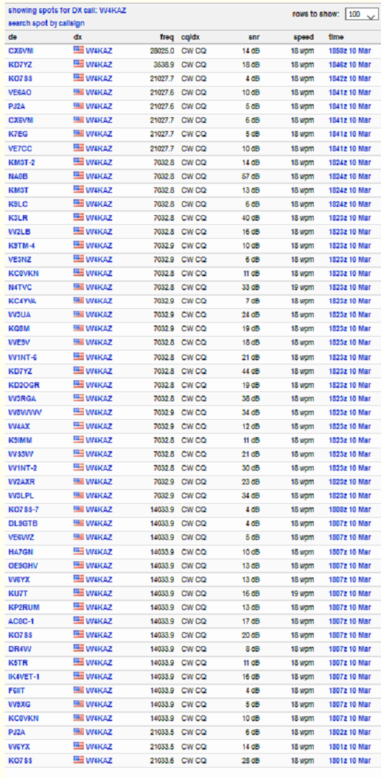
RBN Spots from 40m EFHW at 1800Z on 2021-03-11
The RBN spots from 1800Z show decent results, not too dissimilar from what I am accustomed to seeing from the permanent wire dipole antennas. The test antenna is deployed in a much-less-than-ideal location. The test EFHW horizontal section is running parallel to the horizontal tail of my permanent 160m inverted L, and it is only about 20 feet away. So I’m not too concerned with the locations of spotting stations. I expect to try a POTA activation soon, which will maybe be more interesting.
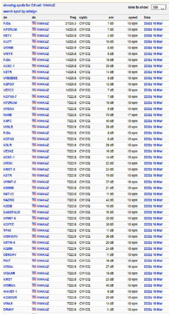
RBN Spots from 40m EFHW at 2345Z on 2021-03-11Â
Likewise the above set of RBN tests run later, near to and just after local sunset @2330Z, show fairly typical results.Â
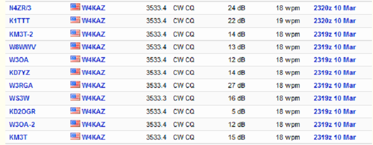
RBN Spots from 40m EFHW at 2345Z on 2021-03-11Â Â *
I expected 80m results to be poor but they were maybe better than my low expectations. Nothing great, but certainly good enough for an easy to deploy portable antenna. Better to have some 80m capability than zero capability.Â
Next Question:Â What happens if I use a different transformer?
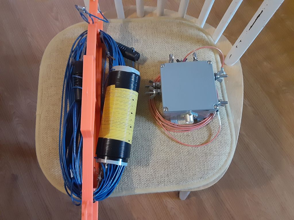
The Initial cut of the antenna and the completed feedpoint enclosure.
Having looked at many of the articles available on the WWW, I wound up favoring the design well documented by G0KYA, Steve Nichols. When modeling the antenna I started out using a coil value of 67.5uh. Then I ran the model using the appropriate value of impedance at each given frequency. The coil as shown above is about 63 turns of 16ga solid insulated wire on a plastic coil form of just over 2 inch diameter. That was right at the limit of the amount of wire I could lay down on the available form. The completed coil resonated with a handy 22pf capacitor at 3.855Mhz, which calculates out to an actual inductance of close to 77.5uh. With the coil value known, I re-ran the model to tweak the initial guestimates with actual values of XL for the model’s load. Then cut wire for the 40m leg as well as the 80m tag end. BEFORE tuning wire lengths are long, 71 feet and 15 feet(about 21.6 meters and 4.5 meters).
Inductor
77.5uh inductor, ~63 turns of 16ga insulated wire wound on a 2 inch plastic form.
The coil form used seems better for RF than PVC pipe, and is a one-off that happened to be in the parts bin, original source un-remembered. I gave it a run in the microwave, and it showed little heating. It’s other quality is it is 1/16 wall thickness, so most of the weight is the winding. The coil is just over 6 inches in length. The second choice for a coil form was going to be fabricated with a few layers of fiberglass and epoxy laid up on some sort of removable former. The measured value is only about 2/3 of the specified 110uh from the G0KYA document(original designer-????), but it comes down to the trade-off question again. This 77.5uh coil should provide 3400 ohms XL at 7Mhz. Hopefully that will be sufficient to isolate the tail. Actual testing should be interesting.
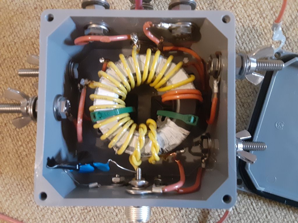
This is the completed transformer installed in terminal box.
It has two ft-240-43 toroids together with a two layer cover of teflon tape to make it more slippery for winding. It is wound with a 2 turn primary and 20 turn secondary. Taps are placed on turns #9, #11, #13, #15, #17 and #20. For the capacitor I used three TDK 330pf 3kV 5% ceramic caps in series. I went that route simply because I had more of that value cap handy than either 220pf or an actual 100pf. There are no crossover turns – that seemed counter productive for multi taps. I would have wound the secondary turns more tightly but needed to loosen the turns up some just to fit it in the box and attach the taps.
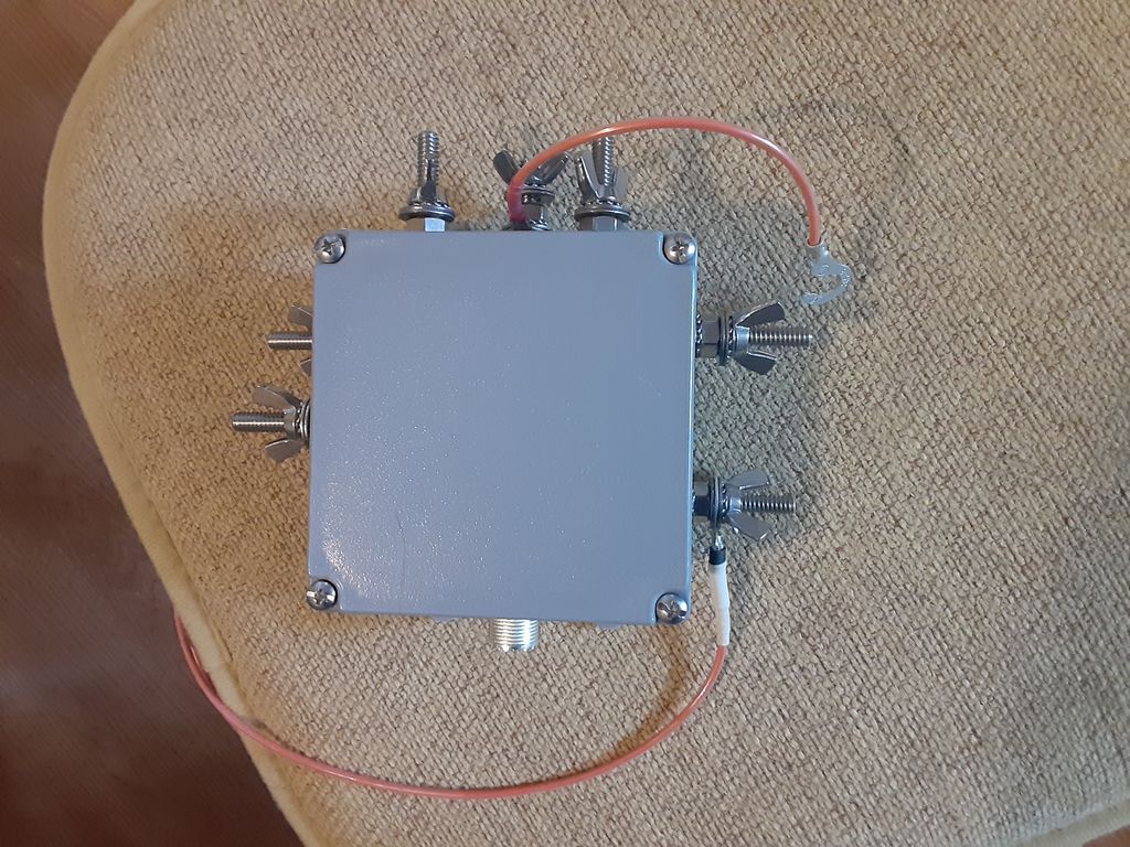
Closed box showing tap wire on top and counterpoise on lower right.
The feed point box is an ordinary Carlon 4x4x2 terminal box. Feed thru studs are all 1/4 stainless hex bolts. I expect to attach the antenna to the 10:1 tap(located top center) and use a jumper to short down to the lower impedance taps as needed for best match rather than have the high impedance taps float. The stud on the bottom right is the ground/counterpoise attach point. If nothing else, the multiple taps provide handy places for extra hardware to replace wing nuts fumbled into the sand.
By w4kaz, created on 2021.03.08 at 15:53:33 | last changed on 2021.03.12 at 22:12:18 |
Just about the only wire antenna in common use I had not experimented with is the End Fed Half Wave(EFHW). So WTF. May as well give it a go.Â
2021 planning had me booking a stay on Cape Lookout National Seashore(CALO) for the end of June rather than the end of July. I tried unsuccessfully to make the reservation in 2020, but could not. Success for 2021. So my FD 2021 will be from Cape Lookout.Â
Given the layout of the cabin I prefer at CALO campground I decided to tinker with the EFHW as a possible solution for allowing multi bands with least effort. The “least effort” factor is growing more important with each passing year. But the EFHW itself piqued my curiosity as well, and it seems it my provide a solution to the “least effort” vs. “works well” conundrum.  Â
So, here lies the experimental portion.  NUMEROUS versions of the classic 49:1 transformer are documented on WWW and in the now ubiquitous scrootoobe video. Version guidelines exist for either 80m or 40m multi band versions. Quite typically I chucked some of that and decided to re-invent the wheel – because what is the fun of experimenting if you are just going to follow the cookbook? Wellll…..not quite that either.
Where to start
Looking for a 40m size and decided to try modeling out a 40m EFHW fit out with a loading coil and tag end to allow 80m or 75m. The idea is to have an antenna that the floppy fiberglass masts would be able to support easily in the normal 20 knot winds typical on CALO. The feed point will be at about 4 feet high as I expect to deploy it. The mast will support the wire vertically to about 30 or 35 feet, depending on which mast is used(Spiderpole or Jackite or K4TMC). The rest of the wire will be stretched out horizontally with the coil supported by a second mast.
This deployment will have 80m or 40m basically functioning as half wave in an L configuration. 20m will probably have a larger horizontal component than the vertical section, and if it works there 15m/10m will provide who-knows-what. i.e., “PERFECT!” – for values of “perfect” where whatever happens is perfect.
Modeling showed best result with the wire between the feed and the load at a longer length than I expected at 70+ feet.  Using insulated wire for actual construction, I expect that to be shorter in real life.  I plan to test with a .05wave counterpoise, and use a 6 foot coax jumper at feedpoint. The real feedpoint will be a current choke at the end of the coax jumper. It seems likely the shield of the coax jumper will act as another counterpoise. Maybe another choke at the radio end.
Transformer Conundrums
The item I had more questions about was the step-up transformer. A lot of conventional wizzdom surrounding the 7:1 turns ratio versions. I chose to give myself more options and provide multiple taps, and use the larger ft-240-43 size toroid to allow 100w.  Hopefully this will give less core heating. Then two turns vs. three turns on the primary was considered. Initially I favored using three turns on the primary.  I expect 80m to be more useful than 10m going forward.  Physical reality – two turns seemed more practical with the 16ga wire I used.Â
The other wildcard I threw into the construction detail was about sticking to the “norms” of putting the taps on nice-and-easy turns ratios.    While waiting on my toroid order to arrive, I stumbled across N8NK’s videos. I found the playlist on EFHW and UNUN’s interesting viewing. The main idea I fortified was to tap the toroid in several different places. That would have been more versatile using 3:1 windings. Even with 2:1 windings I still liked the range of impedances available by placing “irregular” taps, i.e not on the even multiple windings. With 3:1 I had expected to place the taps on every 4th turn. With 2:1 windings I thought maybe every 3rd turn but with 6 taps every 2nd turn was “good enough”.
The only genuine benefit that conventional “even numbered taps” provides is ease in predicting the transformation factor(i.e., 7:1 turns gives 49:1 step up). To switch the flip I decided to tap the transformer at 4.5:1, 5.5:1, 6.5:1, 7.5:1, 8.5:1 and 10:1. (FWIW, that should be stepping 50 ohms up to about: 1013, 1513, 2113, 2813, 3613 or 5000 ohms.) Just for grins, it is easy to test with the ordinary antenna analyzers and a resistor test box(or well stocked junk box). Â
If it is important to your thought process, measure the damn unun to be sure. To simplify, the secondary is actually tapped on turn #9,#11,#13,#15,#17, and #20. With 2 primary turns and just 5 taps on secondary, tapping every 3 turns at #8, #11, #14, #17 and #20 should allow matching impedances of 750, 1513, 2450, 3616, or 5000 ohms. That includes the obligatory 7:1 ratio for purists. I only chose to use the odd taps as an appeasement to my increasingly contrarian curmudgeonly nature.
Precision Optional
 I figure to just use the antenna with the tap that provides the best SWR. I can then produce a cheat sheet for each band. I would like to have a best choice for each band. If it turns out the same tap works best for all bands – so much the better.  If they are NOT all the same tap I also want compromise choices that will allow one tap to allow operation on several bands without moving the tap. Another tradeoff option – sometimes moving the tap will be easy, sometimes inconvenient.
Functionally we can call it good if some doing RBN compares to permanent dipoles prove it to perform acceptably. The truth is I don’t care what the actual step up ratio might be. I just want the antenna to function, and experimentally finding a good tap is “good enough”. We are hoping that the taps provide enough options for multi-band operation with a good match. It will be nice if a single tap is good on all bands. It is not a deal breaker if changing bands requires moving a tap that can be reached at ground level.
Engineer the possible. Mind the trade-offs, because “best” can be the enemy of “good enough”.
Those coil and cap experiments described in part #1 eventually led me to the ‘best’ compromise solution for my situation. In the end I chose to build traps that were resonant below the higher band. I also chose to use cap values on the smaller end of the capacitance value range.
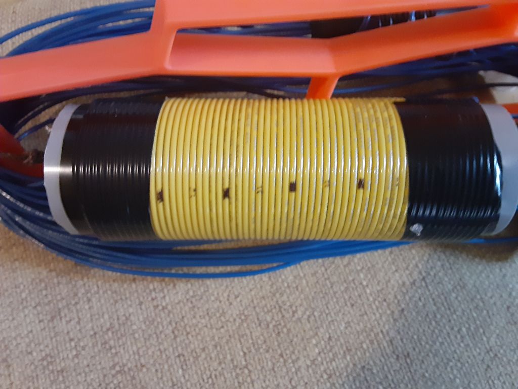
Sample of original 20m trap using 7 turn coil. This trap experienced SWR shifts under xmit at 100w in CW contest.
Revised traps for 20m/40m dipole. The traps use three of the TDK capacitors in series for a total value of 23pf. The 14 turn coil used resonate the traps at 12.65Mhz. Inductance calculated as approx 7uh.
Revised trap for 20m/40m dipole. The trap use three of the 2KV TDK capacitors in series for a total value of 23pf. The caps are mounted in series on a small bit of PCB for a cap value of 23pf. Joints were soldered slightly long with a bit of excess solder in the hopes of a bit of extra heat sinking.
Sadly the Panasonic capacitors are no longer available. Possible TDK replacement are being tested. These TDK caps are physically smaller, and only 2Kv rated. I intend to use these in series/parallel groups once I determine the best values to stockpile. (TIP#x: leaning to several caps in series to extend the voltage rating) (TIP#x: Also decided to mount the caps in slivers of PCB, and use generous solder on the pads as well as not clipping the leads short, all in a hope to have that function as heat sinking).
Antenna Experiments: In testing, these capacitors worked well on xmit for the first 20m/40m trap dipole, but I ran into problems with a 10m/15m trap. Using 33pf with an inductor of about .92uH I had failure of the capacitors while testing the antenna.
As an alternative on 10m I used a bit larger inductance and a piece of rg8x coax as the tuning capacitor(low value approx 8-9pf). No final verdict on this solution yet, but the antenna functioned for light usage in 2019 WPX cw contest. Antennas will be used at 100w levels, so these cap variations should also prove suitable for this project. If weight is not an issue, gimmick caps from coax are viable choices, though I’d not use them with the traps resonant close to the operating frequency.
Alternatively the 20m/40m dipole has now been used in two different contests with success. A second 20m/40m dipole was constructed, using smaller coils and increased capacitance. This second experiment was less stable than the first, with the 20m SWR increasing slowly. Presumably the capacitors were heating and having the same problems as the 15m/10m model.
What Did NOT Work: In the end, the experiments using larger values of capacitance proved to be poor choices for practical reasons. In the case of 10m, the caps failed outright. In the 20m case, the caps showed instability in the form of rising SWR, likely because they were heating. A revised 20m dipole with traps using a larger coil and smaller values of capacitance proved to be stable. Tip#1….Marginal caps can maybe stand the abuse in a trap if the coil is larger.
At this time I also chose to move the resonant frequency of traps a bit farther away(lower) from the operating frequency on new construction. This resulted in :
the dipole legs being shortened,
the impedance on 20m seemed more stable,
The bandwidth on the lower band(40m) was decreased
Precision in component selection becomes less critical
That set of compromises suit me, as the capacitance values are readily available, and the overall antenna length is reduced slightly, without any serious performance compromises as compared to an ordinary single band inverted V. The antennas will be tuned to favor the CW segments, and if needed I will use the radio internal antenna tuner(at the home station) to find a match for SSB if required for 40m. The tuner would likely only be required at the upper band edge if at all.
What worked well enough – Final Versions Constructed: RBN testing of the trap dipole versus a normal 20m dipole showed enough uniformity in results that I am not concerned with trap losses. The end result was a set of dipoles both for permanent use at home and several variations made as light weight as possible for portable operating. The final 20m/40m dipole for the home station was constructed with the traps resonant at 12.650Mhz. A coil with 14 turns close wound on the 1.5″ form was used with a capacitor constructed of several ceramics in series giving a value of 23pf.
A 40m/80m antenna was also constructed. These traps used a coil of 12 turns on the 1.5″ form and capacitors in series parallel for a value of 100pf. Resonant frequency was 6.65Mhz. For future construction this design will likely be modified to move the trap resonant frequency down to the 6Mhz range by increasing the number of turns on the coils while using the same 100pf capacitance value.
A practical benefit of having the resonant frequency away from the operating frequency is that component selection becomes less critical. By selecting a resonant point below the band rather than on or near the band, it is not required to have values to resonate at an exact frequency. Instead, it is only required that each trap resonates at close to the same frequency. This is easier to tweak by adjusting the coil, and it becomes fairly simple to have traps that can be adjusted to within 100hz of one another. The caveat here is that the dipole legs are different based on the trap frequency – but these need to be trimmed to length anyway. [It is possible to easily replicate antennas if the traps are easy to replicate. ] So for a 20m/40m dipole, it makes little difference whether the trap is resonant at 12.5Mhz, 12Mhz, or 13Mhz, so long as the antenna legs are trimmed properly for each.
My experiments show that having the capacitive reactance at the higher operating frequency be in the order of 400-750 ohms seems to reduce the current flow through the caps. Probably this is enough to allow otherwise marginal caps to survive without heating and/or exhibiting SWR variations on xmit. The voltage rating needs to be sufficient, and this can be aided by using several caps in series. The caps in use here are all 2kv or 3kv, and used in series to increase voltage ratings. This is sufficient for 100w levels, but unlikely to survive at 1kw or 1.5kw. I have also mounted them on bits of circuit board to keep the leads short and provide a tiny bit of additional heat sinking. Again, good enough for 100w, but QRO – probably not.