End Fed Half Wave Experiment – Part 1, End Fed Half Wave Experiment – Part 2Â
The “Tune-up-ening”
The first attempts to tune up the real antenna did not go well. I found from the trap dipole project attaching the wires beyond the trap was needed to get the higher bands tuned properly. This worked against me here. With the high impedance on the end fed I was better off tuning the 40m antenna segment without the coil and 80m tail attached. Unfortunately, I wasted a lot of time experimenting/snipping before I decided to detach the inner antenna from the coil.
Once taking that step, I found I had probably trimmed too much off. Tuning for 40m without the coil proved simple enough. After that the other bands were easier too. I was also able to re-attach the coil and 80m tail, and find tap settings and tail lengths to allow operation with good matches on 80m and 20m. With the 20m tails attached 40m operation on the upper edge is possible. With tails 40m SWR was a bit high on CW segment, although possible with a tuner. 10m seemed unaffected by the coil and tail. 15m provided low SWR only with the coil and tail detached, but SWR of 2:1 up to 3:1 with 80m coil and tail.
Antenna Stuff
The coil as wound measured out to 77.5uh, resonant at 3.85Mhz with 22pf of capacitance. It is ~63 close-wound turns on a mystery plastic coil form of ~2 inch diameter, wound with 16ga solid insulated wire. The final wire length in the 40m section is xxft(zz.zm). The 80m tail is xxft(zz.zzm) in length and the portion for ssb(75m) is xxft(zz.zm). To make the choices more flexible for POTA or other portable uses, I have a series of jumpers in several key places.
The first of the jumpers is installed near the feed point. The antenna was trimmed at the feed point for ease-of-access reasons. Since I ultimately decided I had over-trimmed before detaching the 80m coil&tail, it seemed easier to insert a jumper there. This will also allow having an easy method of re-tuning on the fly if it seems necessary in different deployment configurations.Â
The next set of jumpers comes at the junction between the 40m antenna and the 80m coil&tail. There are two more jumpers on the 80m tail itself, positioned to allow choosing between a mid-band SSB section centered at around 3.8Mhz or a CW section centered at about 3.575Mhz. The lower section will allow use on both CW and in the lower 3.600Mhz SSB segment.
The antenna can be deployed with or without the 80m coil&tail. I found that the matches in the 40m and higher segments are much with the tail removed/detached.Â
All Taps NOT Ideal
As described in previous posts, the transformer brewed up for this project has multiple taps, not the fashionable 49:1 single solution. It turned out having the choices of taps gave better SWR matches than any single tap. In fact, only one of the taps worked well for the 15m/10m bands, the lowest impedance 4.5:1 tap. For 40m and 80m, the 8.5:1 tap proved the best choice. 20m SWR curves favored the 7.5:1 tap, although the 6.5:1 tap proved useful with the 80m cw configuration. When configured for 80m CW the 6.5:1 tap provides better than a 1.5:1 SWR across all of 20m. Â
TAP Cheat Sheet
Taps 40m and up, bare wire, NO 80m coil&tail
| BAND | TAP | Best SWR | Â SWR range to expect |
| 40m | 8.5:1 | 7.15Mhz@ 1.2:1swr | Entire band, 1.8:1 up to 2:1Â centered on 7.15 |
| 20m_1 | 7.5:1 | 14.15 | Entire band good favoring CW section |
| 20m_2 | 6.5:1 | 14.275 | Entire band good favoring SSB section |
| 15m | 4.5:1 | 21.3 | Entire band under 2:1 |
| 10m | 4.5:1 | 28.2 | 28.00 thru 28.800 under 2:1 |
Taps with 80m SSB section
| BAND | TAP | Best SWR | Â SWR range to expect |
| 80m | 8.5:1 | 3.825Mhz@ 1.2:1swr | 3.7 thru 3.9Mhz , ?tuner at edges? |
| 40m | 8.5:1 | 7.3Mhz, 2:1 | 7.2 to 7.3Mhz, tuner needed |
| 20m_1 | 7.5:1 | 14.1 | 14 to 14.35 under 2:1 |
| 20m_2 | 6.5:1 | 14.225 | Best choice, entire band good favoring SSB section |
| 15m | 4.5:1 | 21.05 @ 2:1 | 21.0 to 21.35, SWR over 3:1 above 21.35 |
| 10m | 4.5:1 | 28.2 | 28.00 thru 28.800 under 2:1 |
Taps with 80m CW section
| BAND | TAP | Best SWR | SWR Range to expect |
| 80m | 8.5:1 | Â | 3.525 to 3.75 <2:1 |
| 40m | 8.5:1 | Â | 7.2 up under 2:1 |
| 40m_2 | 8.5:1 | 1.3:1@7.3 | 40m jumper ins, useable on cw |
| 20m | 7.5:1 | 14.0 | 14 up to 14.275 < 2:1 |
| 20m_2 | 6.5:1 | 1.5 | 40m jumper ins, all band |
| 15m | 4.5:1 | 21.245 @ 2:1 | Â |
| 10m | 4.5:1 | 28.1 | 28.0 to 28.7 < 2:1 |
 Test Deploy
All tuning was done with the antenna strung up using two Jackite telescoping poles as supports. A 31 footer is used for the vertical portion, and the feed point is at about 4 feet off the ground. The horizontal runs out about 40 feet to the second mast, a 28 footer. The second mast supports the weight of the wire and the loading coil, probably the heaviest portion of the antenna if used.  I ran a 7 foot long counterpoise wire, and a six foot long coax jumper angles down to ground level from the feedpoint to the first choke, eight turns of coax wound on a ft-240-31 ferrite(another 6 foot jumper for that).Â
The short section of straight coax jumper will likely be a second counterpoise for the antenna. The first choke plugs into a second choke constructed of 10 turns of a 14ga wire pair wound on a second ft-240-31 ferrite and mounted in an enclosure. From the chokes a fifty foot long lmr 240 feedline is attached, and all testing was done at the end of the feedline. That simulates the most likely portable deployment.
FWIW, SWR results did not change when the fifty foot section of coax was removed. Will be a curiosity to find out if altering the shape of the deployed antenna changes SWR.Â
Additionally, I toyed around with inserting pieces of wire as jumpers to lengthen the 40m section. These jumpers are inserted close to the feedpoint on the vertical section. I inserted them to try to improve 40m SWR when the 80m loading coil&tail were linked in, as 40m SWR was too high for CW operation without tuner with tail attached. This turns out to be a useful compromise solution. It will allow using either 40m or 80m without adjustment, and 20m/10m can be used with tap change. 15m is the odd man out in this configuration, but could maybe be used with a tuner.
Stress Test Awaiting
Following are some key down stress tests to gauge how well the RBN can hear and to see if there will be any heating in the ferrite cores when at 100w levels. Perhaps a POTA operation would be better.  No “SWR creep” was found when I did 60 second key down tests on the dead bands at 1800Z. Both extreme ends were tested at 60 second key down, 80m and 10m. Then a series of test transmissions that consisted of three repetitions of the test string: “V V V TEST W4KAZ W4KAZ W4KAZ V V V”.Â
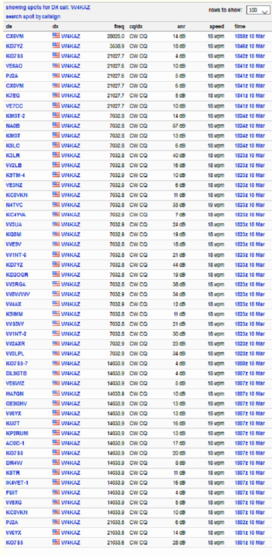
RBN Spots from 40m EFHW at 1800Z on 2021-03-11
The RBN spots from 1800Z show decent results, not too dissimilar from what I am accustomed to seeing from the permanent wire dipole antennas. The test antenna is deployed in a much-less-than-ideal location. The test EFHW horizontal section is running parallel to the horizontal tail of my permanent 160m inverted L, and it is only about 20 feet away. So I’m not too concerned with the locations of spotting stations. I expect to try a POTA activation soon, which will maybe be more interesting.
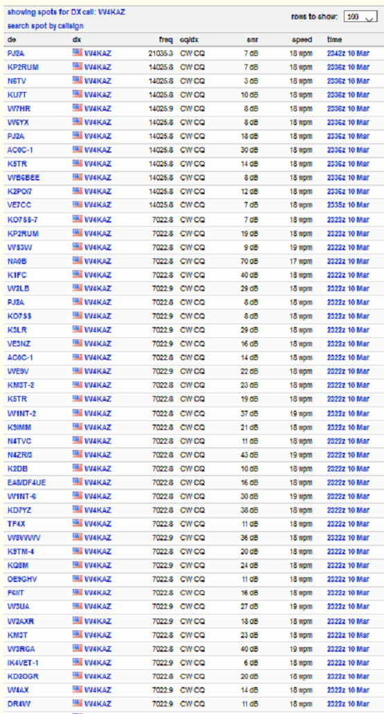
RBN Spots from 40m EFHW at 2345Z on 2021-03-11Â
Likewise the above set of RBN tests run later, near to and just after local sunset @2330Z, show fairly typical results.Â
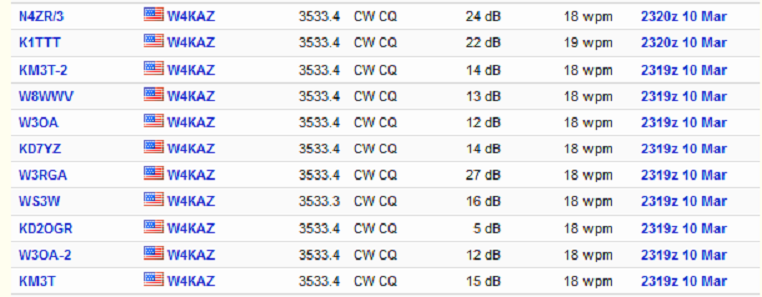
RBN Spots from 40m EFHW at 2345Z on 2021-03-11Â Â *
I expected 80m results to be poor but they were maybe better than my low expectations. Nothing great, but certainly good enough for an easy to deploy portable antenna. Better to have some 80m capability than zero capability.Â
Next Question:Â What happens if I use a different transformer?
see part4Â Â EFHW Experiment – Part 4
*
Leave a Reply