Radio W4KAZ Thanks for stopping by the virtual KazShack. Feel free to comment - I often approve them.
|
By w4kaz, created on 2025.01.06 at 10:01:53 | last changed on 2025.01.09 at 16:30:42 | After a detour to building the 2 band trap dipoles using rg-316 type coax, the worm turned. The failure of a couple of the coax trap antennas due to incomplete sealing and weather proofing the coax became a problem. The antenna at home failed. Two of them. Then the antenna being used for portable ops failed during the 2024 NC QSO party. In the meantime, the home antennas built from coils and capacitors for 40m/20m are still in use 4 years later with no change in resonance points.
Rather than continue with a seemingly fragile system it was time to revert to the coil-and-cap design. Avoiding the cap failures previously experienced on the 10m/15m antenna is addressed by using caps with low enough values to be appropriate for the 10/15 version. So a supply of the TDK ceramic caps was laid in. These caps have 3KV and 6KV ratings. Parts#810-CC45SL3JD080DYGN (example is 8pf SL 6kv) from mouser. TDK Data Sheet for Sl ceramic capacitors.
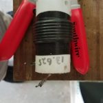
For the 10m trap a value of 10pf was used, with 16 turns of 18ga stranded wire tightly wound on a 1 inch diameter piece of fiberglass tube. (calculated inductance is about 3.25uh) This originally resonated about 27500, but crept up after taping and sealing to 28000. Decided to roll with them as constructed. These may be fragile, too fragile for portable use, as 18ga wire was also used for the connections. NOTE: USE LARGER GA WIRE FOR CONNECTIONS.
The “tricksey” part discovered previously is that using caps with a large enough reactance on the upper band helps them survive by limiting the current actually flowing through the capacitor. At the 100w levels the voltages are less of an issue than the current handling. Using parallel-series combinations can also help, depending on what value caps are available.
The downside is that the inductance value to resonate the trap for 10m becomes relatively large. This makes tuning the antenna for the 15m band “tricksey”. The 15m tail is short, maybe 15 inches from the relatively large inductance used in the trap. When trimming, very small trimmings move the 15m resonance quite a bit more than on a normal 15m dipole. The good news is that the 10m band is only very slightly effected by trimming wire on the 15m side of the trap. The 15m tails needed to be replaced and re-trimmed after trimming a 2 inch bit of wire moved resonance from 20.85mhz to 21.65mhz. oops. SMALL SNIPS FOR 15m tuning!!!!
After trimming, the 10m/15m antenna is good from 28000 to 28750, and also covers the entire 15m band. STOP….DO NOT TRIM AGAIN!
The 20m/40m version is built with a trap resonance at 13.65mhz. The 20m legs are approximately 15ft long. The 40m legs will be about the same. (?actual measurements?) Total antenna length of about 60 feet.
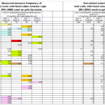
Both of the 2019 home 20m/40m trap dipoles can be easily matched with the Kenwood TS-590 internal tuner for use on 10m as well, which provides options. Worked JA’s on 10m using the 20m/40m trap dipole several times now. The new version for the 20m/40m portable does NOT tune on 10m, probably because of the different value of capacitance/inductance used, or maybe because the new antenna traps resonate at 13.65Mhz instead of 12.5Mhz. The new trapped antenna covers the entire 20m band, with the highest SWR of 1.5:1 at 14000-14015. The 40m band is below 1.5:1 SWR from 7000 to about 7250, with the swr going to about 2.3:1 at 7300.
(For future testing, add turns
Using the new 1 inch o.d.(~25mm) fiberglass form material as the coil form and the TDK capacitors:
Freq———Capacitor——-–# turns calculated——#turns actual——-
27.7Mhz—>10pf————->12 turns (approx)—–> 12 turns, 28Mhz(use 12.5?) (calculated inductance of 3.25uH as constructed)
20.66Mhz–> ?????
13.75Mhz—> 34pf————>16 turns —— ——–> 16.5 turns, 13.65Mhz (calculated inductance 4.04uh)
6.75Mhz—-> 16.33 turns
By w4kaz, created on 2022.06.22 at 20:52:46 | last changed on 2025.01.06 at 10:05:18 | Trap dipoles Part one. .. Trap dipoles Part Two
[edited for links and notes, 2023/07/15] The original trap dipoles were constructed using coils and caps. Using Rg-58 for the coax style trap dipoles was rejected because of the weight and size of rg-58 coax traps. Using RG-58 defeated the primary goal of making the antenna as light weight as possible.
Somewhere I picked up the notion of using rg-174 or rg-316 type mini coax to make the traps. It looks like the voltage ratings on the rg-174 is higher(1100v rms), so that was chosen for the first experiments. If luck holds out, the tiny coax will be sufficient for use on the dipole traps for a full 100w CW. Using the smaller lighter mini coax will allow for lightweight construction from easily available materials that can be easily supported using telescoping fiberglass masts like those available from Spiderbeam, MFJ, or Jackite. i.e., perfect for portable, field day, rover QSO parties, or POTA/SOTA.
The trap calculator program hosted by KC1KCC gave me some starting numbers to work with, and actual trap measurements came out quite close to the calculated values. [alternate calculator at K7MEM]  The traps are built with the coax coils wound reasonably tight to the form, and the coils were taped down with electrical tape prior to taking measurements. These are all wound on small sections of the same sort of plumbing drain tailpieces that are 1.5″ od (38mm od). (e.g., in the US available from Lowes or any hardware store selling plumbing supplies.) The table below are of traps as built and tested with the nanovna.
| frequency |
turns rg-174 |
|
| 27.7 |
3.33 |
|
| 20.66 |
4.33 |
|
| 13.75 |
6.1 |
|
| 6.75 |
10.3 [calculated] |
|
Update, 2024-04-04
Received a new 1 inch o.d.(~25mm) form material that is lighter. testing.
Freq———–# turns calculated——#turns actual——-
27.7Mhz—>5 turns (approx)—–> 5 turns, 24.8Mhz(use 4.5?)
20.66Mhz–> 6.25 turns————> 6.25 turns, 19.65Mhz(use 6)
13.75Mhz—> 8.75 turns ——–> 9 turns, 13.5Mhz & 13.7Mhz
6.75Mhz—-> 16.33 turns
END 2024-04-04 Update
Test Antennas:
The test antennas were built for the CW segments of each band. With the best SWR centered on the xx.070 area it will probably give enough coverage for both CW and SSB operation without a tuner. An 80m/40m version will require tails for 80m adjustments.
Testing of two antennas was done before the May 2022 CQ WPX CW contest. The 20m/15m version tuned easily….after I figured out I was working on that instead of the 10m antenna. Read those labels, because at least I had them labeled properly when they were built several weeks earlier. The 10m/15m version also tuned easily.
[aside: the 15m/20m trap is now in service as the skimmer station antenna, after a recent storm broke the 160m inv-l]
Although I missed the WPX contest, I soon got a chance to do antenna testing at 100w levels.  Both antennas handled the power easily with no signs of SWR rise. Both were tested at 10 seconds, 30 seconds, 60 seconds and five minutes of CW key-down.
Hoping for good conditions in FD to allow testing of the 10m/15m version. Sunspots, do your thing!
[2023-07-15 additional notes] The coax traps began showing swr problems on 10m after a few months in the weather. Expecting this to be a problem with water intrusion. testing the use of WeldBond glue as a sealant. [alternative….Elmers ProBond] Also testing the adhesive as a sort of q-dope to seal the coils on the form.
By w4kaz, created on 2019.09.16 at 09:04:17 | last changed on 2025.01.06 at 10:05:54 |
see: Experimenting With Trap Dipoles – Part 1
Those coil and cap experiments described in part #1 eventually led me to the ‘best’ compromise solution for my situation. In the end I chose to build traps that were resonant below the higher band. I also chose to use cap values on the smaller end of the capacitance value range.
-
-
Sample of original 20m trap using 7 turn coil. This trap experienced SWR shifts under xmit at 100w in CW contest.
-
-
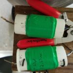
Revised traps for 20m/40m dipole. The traps use three of the TDK capacitors in series for a total value of 23pf. The 14 turn coil used resonate the traps at 12.65Mhz. Inductance calculated as approx 7uh.
-
-
Revised trap for 20m/40m dipole. The trap use three of the 2KV TDK capacitors in series for a total value of 23pf. The caps are mounted in series on a small bit of PCB for a cap value of 23pf. Joints were soldered slightly long with a bit of excess solder in the hopes of a bit of extra heat sinking.
Sadly the Panasonic capacitors are no longer available. Possible TDK replacement are being tested. These TDK caps are physically smaller, and only 2Kv rated. I intend to use these in series/parallel groups once I determine the best values to stockpile. (TIP#x: leaning to several caps in series to extend the voltage rating) (TIP#x: Also decided to mount the caps in slivers of PCB, and use generous solder on the pads as well as not clipping the leads short, all in a hope to have that function as heat sinking).
Antenna Experiments: In testing, these capacitors worked well on xmit for the first 20m/40m trap dipole, but I ran into problems with a 10m/15m trap. Using 33pf with an inductor of about .92uH I had failure of the capacitors while testing the antenna.
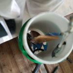
As an alternative on 10m I used a bit larger inductance and a piece of rg8x coax as the tuning capacitor(low value approx 8-9pf). No final verdict on this solution yet, but the antenna functioned for light usage in 2019 WPX cw contest. Antennas will be used at 100w levels, so these cap variations should also prove suitable for this project. If weight is not an issue, gimmick caps from coax are viable choices, though I’d not use them with the traps resonant close to the operating frequency.
Alternatively the 20m/40m dipole has now been used in two different contests with success. A second 20m/40m dipole was constructed, using smaller coils and increased capacitance. This second experiment was less stable than the first, with the 20m SWR increasing slowly. Presumably the capacitors were heating and having the same problems as the 15m/10m model.
What Did NOT Work: In the end, the experiments using larger values of capacitance proved to be poor choices for practical reasons. In the case of 10m, the caps failed outright. In the 20m case, the caps showed instability in the form of rising SWR, likely because they were heating. A revised 20m dipole with traps using a larger coil and smaller values of capacitance proved to be stable. Tip#1….Marginal caps can maybe stand the abuse in a trap if the coil is larger.
At this time I also chose to move the resonant frequency of traps a bit farther away(lower) from the operating frequency on new construction. This resulted in :
- the dipole legs being shortened,
- the impedance on 20m seemed more stable,
- The bandwidth on the lower band(40m) was decreased
- Precision in component selection becomes less critical
That set of compromises suit me, as the capacitance values are readily available, and the overall antenna length is reduced slightly, without any serious performance compromises as compared to an ordinary single band inverted V. The antennas will be tuned to favor the CW segments, and if needed I will use the radio internal antenna tuner(at the home station) to find a match for SSB if required for 40m. The tuner would likely only be required at the upper band edge if at all.
What worked well enough – Final Versions Constructed: RBN testing of the trap dipole versus a normal 20m dipole showed enough uniformity in results that I am not concerned with trap losses. The end result was a set of dipoles both for permanent use at home and several variations made as light weight as possible for portable operating. The final 20m/40m dipole for the home station was constructed with the traps resonant at 12.650Mhz. A coil with 14 turns close wound on the 1.5″ form was used with a capacitor constructed of several ceramics in series giving a value of 23pf.
A 40m/80m antenna was also constructed. These traps used a coil of 12 turns on the 1.5″ form and capacitors in series parallel for a value of 100pf. Resonant frequency was 6.65Mhz. For future construction this design will likely be modified to move the trap resonant frequency down to the 6Mhz range by increasing the number of turns on the coils while using the same 100pf capacitance value.
A practical benefit of having the resonant frequency away from the operating frequency is that component selection becomes less critical. By selecting a resonant point below the band rather than on or near the band, it is not required to have values to resonate at an exact frequency. Instead, it is only required that each trap resonates at close to the same frequency. This is easier to tweak by adjusting the coil, and it becomes fairly simple to have traps that can be adjusted to within 100hz of one another. The caveat here is that the dipole legs are different based on the trap frequency – but these need to be trimmed to length anyway. [It is possible to easily replicate antennas if the traps are easy to replicate. ] So for a 20m/40m dipole, it makes little difference whether the trap is resonant at 12.5Mhz, 12Mhz, or 13Mhz, so long as the antenna legs are trimmed properly for each.
My experiments show that having the capacitive reactance at the higher operating frequency be in the order of 400-750 ohms seems to reduce the current flow through the caps. Probably this is enough to allow otherwise marginal caps to survive without heating and/or exhibiting SWR variations on xmit. The voltage rating needs to be sufficient, and this can be aided by using several caps in series. The caps in use here are all 2kv or 3kv, and used in series to increase voltage ratings. This is sufficient for 100w levels, but unlikely to survive at 1kw or 1.5kw. I have also mounted them on bits of circuit board to keep the leads short and provide a tiny bit of additional heat sinking. Again, good enough for 100w, but QRO – probably not.
By w4kaz, created on 2019.09.15 at 15:29:37 | last changed on 2025.01.06 at 10:06:15 |
The Project and Situation: After quite a bit of trying over the past 15 years to find the best way to pull dipoles up into the closely packed trees in the yard it is clear the options are limited. Having the dipoles favor the NE/SW directions are the goal, but the arrangement of the best supports make this difficult. To beat this problem a combination of single band and multi band fan dipoles were used. [No, the “chainsaw solution” is not an option – yet.]
The primary supports are now occupied with supporting a 160m inverted L and another with a vee dipole for 80m. These are not high enough for direction to make much difference, but are in convenient locations. So everything else needs to fit around those two primary constraints.
The current problem is that there is really only one support that easily allows stretching out the legs of a 40m dipole in the desired directions while also achieving a good height for 40m(almost 50′). The other high supports will only allow the antenna to be deployed favoring a N/S direction(i.e., legs are stretched out E/W).
Using fan dipoles has come with its own practical problems. The dense tree branch coverage tends to tangle in the multiple wires of the legs. Then the fan legs have become entangled in heavy winds. So it is both a problem deploying the antennas, but also the SWR issues when legs are entangled after bad WX. An ongoing maintenance issue.
Alternate solution: trap dipoles. With dual band trap dipoles, it seems like it may be easier to arrange the antennas in favorable directions AND at good heights. The traps are relatively small compared to the mess of multiple wires on a fan, so also maybe it will be a bit easier to navigate dense branch cover of the biological deciduous antenna support structures. The downside is in the extra effort required in constructing the traps, tuning them to desired frequencies, and tuning the antenna legs for each desired band.
What’s the frequency, Kenneth?!? Using EzNEC 6 I ran models with trap data. Based on those results I initially decided to use traps tuned for just above the top frequencies of any given band(e.g., on 20m tuned for 14.400). I’m willing to live with the trap losses for the advantage of maintenance simplicity. Models showed tuning traps for the top end resulted in wire lengths that are the same as a single band dipole, or slightly longer. I then chose to build antennas with traps above the high end of the band based on the following.
- A trap resonant frequency above the band results in the dipole wires being the same length or slightly longer than the single band dipole at the trap frequency
- A trap resonant frequency below the band requires the dipole wires to be shorter than a dipole for that band. This might be worth pursuing if trying to reduce the antenna length.
- there were already a few spare dipoles laying about, and if the traps project flopped they would still be usable mostly intact if traps designed above band,
- I’ll probably be mostly using them on CW so maybe a tad less loss with trap rez at opposite end
- the gut feeling that a 20m trap resonated at 13.900 would maybe have more loss than the trap at 14.4 when used at 14.025.
- NOTE: SEE Part 2 for notes on how these initial assumptions changed!
Research: The traps will inevitably add unwanted weight to the antennas, and I wished to keep them as lightweight as possible. The reasoning for light weight was to extend the project to portable dipoles deployable on telescoping fiberglass masts. So I ruled out using one of the many coaxial trap designs simply to save weight where possible. For coil forms I chose to use small pieces of 1.5″ plumbing waste pipe cut from small sections of what is sold in the US as a “drain tail piece”. This is thin wall pipe, and much lighter than ordinary schedule 40 PVC. The second form material tried AND ABANDONED is 3.4 inch PVC sched 40.
Excluding the coax trap articles, there are relatively few trap dipole projects written up or documented in places accessible via internet searches. The best[most relevant] source is an ARRL antenna book article on a 2 band trap dipole. W8JI also has some interesting trap info published. Although it does not cover the specifics on the options I chose, it led me to the final result. My choices were made based on materials already on hand(wire, capacitors, and coil form material). Engineer the possible.
Initial Trap Construction: The available values of capacitors also drove the selection of trap resonant frequencies. On this point I made an effort to follow W8JI’s information and make the traps resonant off of the desired operating frequencies to minimize trap losses. Beyond this guideline I could locate nowhere any info to indicate if certain values of inductance vs capacitance were better or worse. A larger inductor will allow the antenna to be shorter overall, but the length of the dipole legs was not a restricting parameter for my project. This was merely about having the dipole resonant on 2 bands. Also, the capacitors are 2KV and 3KV 5% tolerance ceramics from Panasonic that I have used previously in band pass filter projects with great success. (NOTE: MORE ON THIS LATER!!!)
Coil Guidelines????: Guidelines for winding the coils are also a bit of guesswork, beyond W8JI’s testing results that show the highest losses occur on the resonant frequency of the trap. I simply started with the inductors, targeting a value of 6uh, initial turns counts generated by a random calculator found via internet search. Then trial and error on actual coil winding. Calculated inductances are based on trap resonant frequency measurements recorded and on the assumption the 5% caps were the most accurate component. Inductances are then calculated from cap face values and resonant frequency.
Test coils for the traps were close wound with #14 THHN stranded housing wire. They were close wound by hand as tightly as possible onto the forms. Coil Q is probably lower than it could be, but the close winding was a compromise accepted for ease of construction and ease of replication. Four inch lengths of 1.5″ waste pipe and three inch lengths of 3/4 inch PVC were tried. The latter were discarded as unsuitable.
Experimenting With the Coils and Caps: The 5% Panasonic caps on hand typically measure very close to the marked nominal values, much better than any 5% or 10% silver mica caps I have used in similar projects. I found that coils wound with similar technique and the same number of turns would reliably resonate within a range of +/-100 to 200hz. Generally the accuracy and reproducibility is better at 7 and 14 Mhz than at 28Mhz. The coils at the higher frequencies have fewer turns, and smaller differences in inductance and capacitance have a larger effect on resonance.
-
-
Initial coil test data
A group of several capacitor values were used along with an MFJ-259C as a grid dip meter to find the resonant frequencies. Pickup coupling coil was a coax jumper terminated on the business end with gator clips and a short length of #14 wire formed into an adjustable sized loop.
Some initial experimenting with the number of turns on the inductors was based on these available values of fixed capacitors. The first inductor was 12 turns on the 1.5″ forms, then resonance was tested with the values of capacitance that were on hand, or able to be easily derived using series and parallel pairs. It was then relatively simple to find the number of turns needed to be able to produce a trap resonant at a given frequency. I also wound coils on the same form material using 7 and 9 turns, and measured resonance for these.
Experimenting With Trap Dipoles- Part 2
|
|