Radio W4KAZ Thanks for stopping by the virtual KazShack. Feel free to comment - I often approve them.
|
By w4kaz, created on 2010.09.20 at 08:22:27 | last changed on 2010.09.22 at 07:01:24 | Put together a WinKeyer2 in a couple of hours two weeks before Field Day. This accessory was added as part of the plan to have the SO2R station capability operational with either USB or serial ports on the logging computer. I chose the version with a serial port, and plan to use it with a serial to USB conversion dongle. In essence, the shack will be forward or backward compatible with the computer hardware, allowing the SO2R to be feasible with whatever crappy piece of computer I have available at any given moment, from an old dos box to brand spanky new.
The keyer kit itself was built with only about 30 minutes of plugging and soldering. The kit was missing a couple of capacitors, but they are common values which I had in the parts box. It took another couple of hours to get the enclosure drilled and nibbled out – including a db9-sized hole in the wrong place. Oops. On hindsight, a simpler plastic enclosure would have been easier.
The finished product worked without any re-work. The WinKeyer2 is the newer release of the serial port version of the kit. I tested the kit out using a USB to serial converter and the “wktest” program available for download on the K1EL site. After a quick test and config with the wktest program, I brought up writelog and tested that. Flawless performance.
Hooking up the paddles was a bit less satisfying. I’m not terribly proficient using paddles and a keyer, and the WinKeyer2 seemed a bit temperamental with my shaky fist. Maybe after more practice it will become easier. But for now, the paddles will be routed through the logikeyer CMOS4, and the paddles will be combined with the computer generated CW from the WinKeyer via a “Y” connector going into the CW input.
I also have the same problem using an MFJ keyer I have on hand. I’m not sure why that is, but so far the Logikeyer and the keyer built into the K2 are the easiest to use of those available.
One quirk I found with the winkeyer(or my understanding thereof) was related to the pot setting for the keyer speed. Starting the programs(either logging program or “wktest”) while the speed pot was set to maximum caused a bit of confusion. To allow computer control of the speed setting, it seemed necessary to disable the speed pot via the software.
Part of the learning curve.
By w4kaz, created on 2010.04.06 at 06:11:05 | last changed on 2011.02.16 at 09:26:02 | This home brew SO2R controller project follows the “old-n-busted” theory, and is based on the design by N6BV in the ARRL Handbook, as well as some input from K4QPL. In summary, it is built around the use of an LPT port for computer control of the CW, PTT, Radio A/B, and band data. As previously outlined, the LPT port is less expensive and easier to accommodate – even if obsolete. Hence “old-n-busted”. I expect to be able to bridge the gap to USB at some point by adding a K1EL WinKeyer, and the Piexx SO2Rxlat dongle.
The rig control is still accomplished via a serial port for each radio. The LPT parallel port is used for PTT, CW, transmit focus, and band data for one radio. The K2 band data is a separate option not installed in my K2[another void the Piexx SO2Rxlat dongle will solve].
As it stands now the only parts missing for a conversion to USB device control are the WinKeyer and SO2Rxlat devices. Everything else in the SO2R control chain is home brew.
There are several resources available that block diagram the components needed inside the shack for SO2R[e.g.,see DL1IAO, for the W5XD SO2r Box].  For ease of use and construction, the heart of the SO2R box breaks down into four logical units which were built into three separate boxes.
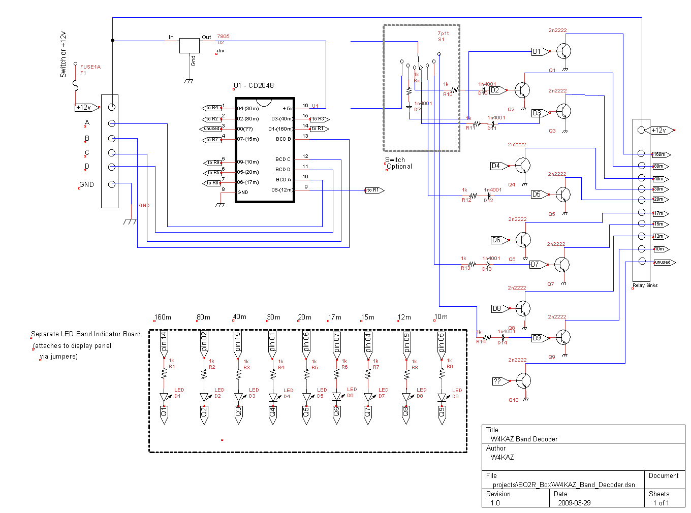
Band Decoder: One of the peripheral boxes will provide automated band switching driven by the logging program[or directly from a radio] by acting as the band decoder. Most logging programs provide band data in the “BCD” format, and Yaesu radios provide that format via their hardware dedicated band data outputs. The binary coded band data make the design of the decoder relatively simple. In hindsight, it seems like a good idea to expand this component’s abilities by using a set of relays to provide for either positive or sinking switching. This is a consideration for driving band pass switches or antenna switches, and is also a design factor for home brewing those components.
 The internal view of the band decoder
More band decoder photos.
Band decoder schematic. PNG Image, PDF file
For those looking for an inexpensive band decoder solution, the Unified Microsystems band decoder looks like a real bargain and could easily be incorporated into a home brew design. To build a band decoder, it is probably better to start off with the Unified Micro unit and build the support hardware around it.
Audio Switch: The second is a simple peripheral to the main SO2R box is a simple remote switch. This device itself is simple, yet it really makes the SO2R a lot easier. This device was subdivided into two physical component parts. The actual relay board that switches the audio was built on its own small pc board and mounted within the SO2R box. The user controls are mounted in a small project box. The small box sits just above the keyboard on the desktop.
For my own preferences, it seemed better to have one small “remote” user control box for switching in the heat of battle. The remote has a rotary switch to control the headphone audio, and it can choose either radio individually, stereo with one in each ear, stereo with left and right reversed, or it can be set to have the audio follow the transmit focus. It also has a momentary contact switch for each channel, which can be used in stereo mode to listen to either channel for as long as the switch is depressed. The remote switch control is connected via a Cat-5 cable to the SO2R control box. The control box and its rats nest of wiring can be placed away from the station controls.
Remote: The momentary contact switch feature will soon be enhanced to correct an original construction oversight. Parallel connections for the momentary contact switches will be added to allow using a footswitch. That will provide hands-free audio switching when in stereo mode. That is important, as I need the hands free to type and deal with CW and radio tuning. Hat tip to K4QPL for the idea.
Remote locating allows both the main SO2R box and the band decoder to be located away from the other major components in the station. That highlights the single caveat I experienced – RFI on SSB. After experiencing RFI problems during ARRL SS SSB, both of these units still need some attention paid to choking RF on the interconnects. Re-locating them a bit further from the RF hot spots and coax connections should also help with the RFI. Judicious and liberal use of clamp on RFI chokes seems to abate the problem.
For some reason, the K2 seemed more susceptible to RFI than the Yaesu FT-920. The RFI source there turned out to be on the PTT line. A combination of ferrites and a diode in the PTT line finally tamed that hotspot. Note: in the PTT line, the PTT hot is at the radio’s mike connector, and it really didn’t sink into the thick head right away.
 W4KAZ SO2R control box
More SO2R box photos
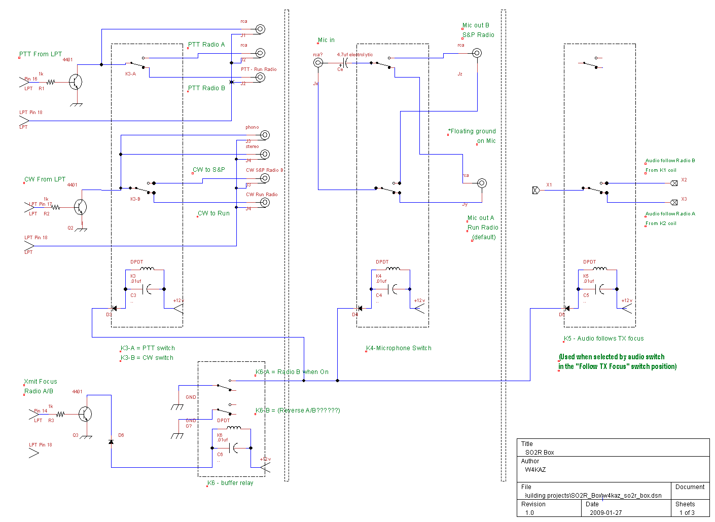
SO2R box schematic PNG Image, PDF file
Audio switching schematic PNG Image, PDF file
SO2R Box: The guts of the system all reside in the main SO2R box. It has inputs for headphone audio from each radio, CW inputs, PTT inputs, and microphone audio inputs. There is also an LPT Db-25 input for connection to the computer. The set up is designed to receive control input from the computer LPT port to drive some of the switching and provide band data.
The main box contains two separate components. Two small perf boards were used to simplify construction. One board contains switching for the headphone audio. The other board handles switching for the CW, PTT, focus control, and microphone audio. The audio is normally switched via the switch remote, but it can also be slaved to follow the logging program’s transmit focus and be controlled from the main SO2R board.
Future Migration to USB:
In order to migrate to a logging computer with USB ports, it should be a minor change to replace the LPT cable with a USB connection via the Piexx SO2Rxlat device. By making the components LPT port compliant, the SO2R capability can also remain backward compatible with an older computer that has no USB support, running Writelog. Just in case the only option is an ancient junker from someones junk bin. The SO2RXlat will also provide band data for both radios via a single LPT DB-25 connector.
Postmortem:
The total cost in parts was not large. The 4401 NPN transistors, relays, connectors, bypass caps and diodes were all generic ‘project part’ items I have been accumulating over the past several years. I have gravitated towards using RCA connectors because of the availability of inexpensive sheilded RCA cables and the low cost of the connectors. The CD2048 IC for the band decoder was a dedicated purchase, and were around $1.98 USD. The amount of time put into construction, the biggest real expense, amounted to about 15 total hours, spread over a long period in several hour long increments. I spent more time debugging the RFI issues.
The RFI is probably partly due to using plastic enclosures, but these enclosures were easy to come by. In hindsight I would add ferrite beads on to all interconnects inside the boxes. The ferrites on the interconnect cables create a bit of additional clutter and impede quick wire pulls. Kludgy.
The remote switch has since been modified to add a jack for an external switch to concentrate both channels on either the left or right radio. This will allow for use of a foot switch and will allow hands-free audio switching.
By w4kaz, created on 2010.01.31 at 13:19:21 | last changed on 2010.01.31 at 13:29:34 | After building the 80m/160m splitter, it seemed like the signal levels from the K9AY were down a bit, probably from losses in the filters. So after looking around at pre-amps, and procrastinating on buying the Ar2 preamp, I again landed on the W7IUV site.
W7IUV has updated his preamp schematic, and it looked easy enough. Building the project was simple after gathering some suitable parts.
Trying the pre-amp out seemed to show that it was more or less filling the desired role quite well. With the preamp engaged, levels from the K9AY were now on par with signal levels from the transmit antennas on both 160m and 80m. The preamp is installed in the shack just ahead of the band splitter.  Noise levels on the RX system were down about two to three S units from the TX antenna in these moderate noise conditions.
During the 160m contest this weekend, the RX system got its chance to proove itself. Noise levels here were moderate – not as quiet as good winter conditions, but not S9+ summertime noise either. The RX antenna with the preamp turned on was always the best choice on weak signals in these conditions. It also necessary to switch the K9AY around a lot – signals were not always best in the expected direction because of higher noise to the north.  The southeast direction was dead quiet, but from here in central NC there isn’t much to listen to on 160m to the SSE. The actual compass direction on the SE leg is about 10 degrees south of southeast.
So the short version is that the preamp is an improvement when splitting the RX antenna for two radios. Â
Future projects/curiosities:
- Try moving the preamp out to the base of the K9AY, probably in a new K9AY switch box
- Test the RX with the splitter removed, preamp on/off.
Â
By w4kaz, created on 2009.12.19 at 05:32:14 | last changed on 2021.05.06 at 21:14:16 | Some suitable and inexpensive parts for future projects. A continuing aggregated list of Stuff I Use To Play Radio.
- Small signal DPDT relay: (For K9AY et al, & 12v control switching)
- TX Antenna switch relays:
- P&B RTB14012F(SPDT, 12A), RTD14012F(SPDT, 16A)
- P&B RT424012F(DPDT), P&B RTE24012F(DPDT)
- AZ755-1C-12DE(SPDT)American Zettler power relay for KK1L & KOxxx projects – AZ755 Data Sheet
- AZ733-2C-12DE(DPDT)American Zettler power relay, 12A
- note: The Zettler and P&B DPDT relays are interchangeable(pin layout compatible) if the power ratings are sufficient for your application and both poles of the P&B are tied together and used as an SPDT[i.e., for the KK1L 6×2 switch project]
- Fujitsu, VSB12STB SPDT, 12V, 16A(data sheet marked “to be discontinued” (??replacement??)
- ?? SRUDH-SH-112D1,000 ??
- ??OMI-SH-112L,394??
- cd4028: Logic chip for band decoder to drive 2n2222 or 4401
- lm3914( Obsolete?): DL6RAI BevBox – Logic chip for resistance driven switch, drives pnp(part#?)
- Panasonic capacitors(data sheet on 1/1/2018) from NVARC project. Many RF uses. ( Mouser part)Â TDK: comparable replacement TDK CC45 Series of ceramic caps
- Capacitors:  ????CDE DPPM16D1K-F ????  ????TDK CK45-R3AD102K-NR???? ???? Murata DEBB33F102KA3B????  Kemet Gold series Kemet C330C201JHG5TA
- Toroid King – Iron powder and ferrite toroids, W3NQN toroid kit
- Kelvin – Loads of cool hobby stuff
- Toroid core, type 75 material, Digikey #240-2524-ND (Steward)
- TDK clamp-on ferrite(11mm fits RG-8/RG-11), TDK data sheet, Mouser#810-ZCAT2132-1130BK
- Velleman 8 channel relay card kit, with rs-232 programmed PIC
- McMaster-Carr, coil form edge trim, pn 85085K8 (also bare copper wire, pn 8873K51)
- Dry Box, MCM Dri-box 285 Outdoor Waterproof/Weatherproof Box MCM part #: 21-11160
-
?? more porridge pleeze ??
last update 2010-04-22, w4kaz
By w4kaz, created on 2009.11.01 at 06:44:34 | last changed on 2016.06.09 at 08:04:39 | edited and amended11/02/2009, kaz
Here is a small project that will work along with the K9AY RX antenna, and solve a minor SO2R problem in the KazShack.
Currently theK9AY feedline comes into the KazShack directly to the RX input for one of the transceivers. I wanted to have a way to share the antenna between the two radios without connecting the RX inputs of each rig directly to one another(RF isolation), or manually swapping the feedline between radios.
There are some comments in various places about using the W3LPL RX bandpass filter design to split the bands to multiple destinations. The NCJ article “Distributing Receive Antennas” by K3NA and W2VJN is a very handy and well explained reference.
This was also desirable here in the KazShack, which sitsin the shadow of the 50KW WPTF on 680kc broadcast transmitter. Rolling the W3LPL filters was done using some T-50-3 toroids and NP0 and high accuracy monolithic ceramic capacitors from the parts bin. The filter is built dead bug style. Each band is on opposite sides of a single piece of copper clad board. Basically, the input is fed to each of the filter banks, and the 160m and 80m bands come out separately, each isolated from the other.
The coils for each band are identical within the band(i.e., L1=L2=L3), so after winding each I used the MFJ-259 to resonate each coil to the same frequency using the same capacitor. After soldering everything together, a quick test with the antenna analyzer into a dummy load showed each section to show minimum SWR right where I wanted it. No other tuning was required. Almost too easy.
Left alone at that point, I could feed either radio from either band, but there needs to be a switch of some sort to eliminate the need for swapping coax feeds during the heat of the action. This appeared to be another ideal application of the small signal relays that were also on hand. Using a single DPDT relay, the filter outputs can be switched between the radios with the flip of a switch. A toggle switch mounted on a remote panel is used for convenience . Simple but effective.
The remote panel is a smallsection cut from 1’5 inch(about 38mm) aluminum angle stock. I pre-drilled pilot holes for future use, and installed the switch for the RX antenna splitter, as well as a control for a planned 40m remote antenna switch. The “panel” is then attached to the inside edge of my home brewed fold out station cabinet. The cabinet is filling up fast – not much room for any more equipment in there.
Using the switch is going to make swapping the low bands from one radio to the other a snap. Literally as easy as flipping a switch. The band pass filters will also help isolate the radios from one another in the SO2R environment, as well as reducing the broadcast band harmonics.
There is a bit of signal loss in the filters, but probably not enough to be significant while operating. Hopefully the much lower noise levels on the RX antenna will offset these slight losses. I have not felt a need for an external RX preamplifier before now, but now I am looking at the ARR 1-30. It would be nice to boost the RX signals to parity with the noise on the TX antenna. That might reduce the amount of volume control “riding” needed when looking for the best RX on a contact when toggling between the RX and TX antennas.
Yet another fun little project. It isn’t as much satisfaction as growing an entire rig from scratch, but it is always fun to put a useful bit of home brewed kit into action.
PHOTOS (Full set of photos on external page)

SCHEMATIC:

PNG image of schematic for W4KAZ’s version of the “W3LPL RX band pass filters” built as an antenna splitter and switch.
By w4kaz, created on 2009.06.11 at 05:09:57 | last changed on 2009.07.06 at 10:05:40 | Part 5 of the W4KAZ filter project series discusses filter losses, an idea for getting a very rough S-meter calibration, and trying to estimate the out of pass band attenuation provided by the filters.
The Losses:
The filters do have losses in the pass band. This is known as the insertion loss, and is reported in db. When discussing the pass band, we want the losses to be as low as possible, or approaching 0.0db of loss. The old rule of thumb is for every 3db of loss you are losing about half of your power. So, 100 watts of RF transmitted through a 3db loss component means there is only 50w coming out the other end.
Run that through the loss formula…. db loss = 10*[log(100/50)] = 10*log(2) = 10*.30103 = 3.01db of loss.
Since loss is defined as a ratio of the actual power levels, a simple watt meter and dummy load can be used to measure the losses of a component in db. That gives a nice yardstick for comparision to known commercial filters. The accuracy of the wattmeter is an issue, but part of the game is to compare the values I come up with against values measured with better test equipment. If I ever manage to hook up with one of the guys who are willing to help with that.
The set up to measure the loss in the pass band is simple.
Transmitter–> filter –> watt meter –> dummy load
By replacing the filter with a barrel connector, you can get the baseline power. The watt meter on hand here is not sensitive or accurate enough to use the same technique for measuring signals outside the passband. Not if the filters are working. 😮
Aside: This is also a good way to test a piece of unknown coaxial cable. Rather than rely on an estimate of what the loss should be for a known length of similar cable, it is pretty easy to measure the loss. A quick computation of the loss into db gives you a yardstick on the quality of the cable by comparing it to known losses specified by cable manufacturers.
The Guess-Estimate:
Anyway…. My set of NVARC filters came in measuring actual losses between 0.6db to 0.8db, and about 1.0db when installed in the integrated switch box. The set of K4VX filters came in at 0.3db to 0.6db.
The problem is that the insertion losses in the pass band tell little about their effectiveness on the 2N or N/2 harmonics.
The only tool available in the KazShack for measuring this type of loss turns out to be the S-meter on the receivers. Receivers are quite good at hearing RF. Kinda their whole purpose in life, right? The new problem is the unknown scale of the S-meter. Is it telling us anything useful?
So: How to calibrate the S-meter?
Okay. I couldn’t solve that one. Is there a possible work-around, or a way to determine the existing calibration of the S-meter?
This puts me off into an area that may eventually turn out to have little real-world validity, but here’s what I came up with. The FT-920 has a three step attenuator pad which is a known quantity. Assuming a simple resistance pad can be easily calculated and implmented by engineers capable of designing such an otherwise comlpetely slick gizmo. For some reason the pad is coincidentally in 6db steps, giving 6,12, and 18db. How convenient. 😮
The unofficial rule of thumb is that an S-unit is supposed to be 6db, with S-9 the 50 microvolt level. So with 18db attenuation, an S-9 signal should be knocked down to S-6. I don’t have a 50ֶ standard, one of countless other things I don’t have, but I am able to generate a signal at various levels. So I decided to use the attenuator pad to calibrate the S-meter markings. Although I may have no idea what level actually causes the meter to read S-9, I CAN use the known values to figure out the values from S-9 down, or S-9 up. I still don’t know the actual signal levels or what signal level corresponds to an S-9 meter reading, but the scale allows measurement of the relative differences in known quantities. In this case, that is exactly what I need.
What this gives me is a round-about way to guess-estimate the effectiveness of the filters where it counts, on the sub harmonics or harmonics. If I know the value of attenuation causing a signal drop from between S-9 to S-2, inserting a filter that causes that same drop will have that amount of attenuation on that frequency.
Nothing is ever THAT easy. S-meters are known far and wide for non-linear behavior, right? Sheesh. But life is full of surprises.
Previous in series: Band Pass Filter Fever – The Kludgy Switch Box – Part 4
Next in Series: BPFF – The Guess-timated Scale and actual Guess-timates – Part 6
By w4kaz, created on 2009.06.01 at 06:59:33 | last changed on 2009.07.06 at 10:10:07 | Part 4 of the W4KAZ filter project series comments on the process leading up to the integrated box full of NVARC Ugly filters for use in the KazShack. The quest continues.
Notes: Link to photos of the project at bottom of this page. If you want to read about the project from the beginning, go to the”Band Pass Filter Fever” series page.
Part of the project goal is to put all of the NVARC filters into a switched box to allow for SO2R and use at Field Day and on IOTA expedition. The original idea was to use a simple rotary switch. Somewhere along the way the idea morphed into using relays set up to allow control from a band decoder.Toying with the relay switching idea brought up a couple of issues that I chose to avoid. Instead, the individual filters were tied together with a two pole ten position switch.
A previous project resulted in a seven position remote antenna switch.That switch is lossy on 15m and 10m because of the point to point dead-bug style wiring. I didn’t see an easy way to avoid this problem, and I’m not set up for PCB design/manufacture. Using PCB’s and strip line runs would solve the issue. I have an idea for making strip lines that may work, but it is a bit Rube Goldberg-ish, so I chose to shelve that temporarily.
So, back to the rotary switch. I had a 2-pole 10 position switch in the junk box. The contacts are silvered brass, and seem beefy enough for the job, so I tested it out by wiring up the input/output to a bypass position.
Ick. Needless to say, it is not an ideal solution. The loss through the switch alone on 10m is about 0.6db. Losses are lower on 40m and 80m, just barely measurable.
So, WTF. I used it anyway. More suitable switches are a bit pricy if bought new, and this one was already in my sweaty little hands. Impatience, “good enough”, and zero cost won out over quality. Engineer the possible.
After all of that hand wringing was done, some other practical construction choices needed to be thought out. The end goal of constructing a switched filter box could have been implemented in several ways.
Method 1: Use the existing set of filters, switching them in via an external switch box, all connected via a rat’s nest of coax jumpers.
Method Zwei: Build another set of filters into a larger enclosure, and incorporate the switch into the new design.
Method III: Use some less aesthetically pleasing choice that will also benefit from poorly conceived and hacked together engineering practices.
Well the choice was clear – use Method III!
The rationale unfolded as a matter of “least inconvenient compromise” rather than “optimal design”. I was limited in the number of parts available. That was the primary limiting factor for method 2, not enough capacitors of the proper values on hand for a full second set of filters. Keeping the individual filters available was desirable for the sake of future flexibility, so ripping them apart and re-assembling was not considered.
Parts count also played a part in ruling out method 1, as it would use up 20-plus pl-259’s, plus the coax.
My compromised solution was to use the individual filters with a slight modification. Rather than remove the so-239 connectors, I merely tacked on a pigtail of coax for the runs to and from each switch. It is a compromise in every way, electrically, mechanically, and aesthetically. But it sure was simple.
It also seemed to work electrically better than I expected, as none of the loss figures vary substantially from the losses I would expect from the switch plus those of the original individual filters. In other words, the db losses through the filter added to the db losses from the switch in bypass add up to the total loss, when each band is measured separately.
The completed box shows losses on all bands of approximately 1.0 db. This is a bit odd, given the losses of the switch itself vary by band. But the insertion losses of the filters are lowest on 10m, and highest on 80m. Since the losses through the switch component are high on 10m and low on 80m, they all seem to coincidentally hover in the 1.0db range.
It appears that the insertion losses on 40m and 80m filters are a bit higher than the NVARC spec. This is probably because of compromises made in the physical construction, as the coils in those filters are closer to the sides of the enclosure than they should be. They were built last and the enclosure used were more difficult to work with due to their non-standard construction.
The insertion losses in the 1.0 db range are significant enough to be a concern, but everything is a compromise. This is the compromise I’m required to make for SO2R without outlay of more ca$h. The ca$h reserves are currently at less than optimal levels, but there is a lot of that going on. It will be an even larger compromise operating with low power than it would be if the filters were followed by an amplifier, but such is life. Engineer the possible!
In the grand scheme, the finished NVARC box shows about 0.2db more losses than I could expect from the commercial Dunestar series, and maybe 0.4db more loss than is expected from the W3NQN variety. On a positve note, this one cost less than $50.00USD in materials, not to mention everything I learned during the construction. The time required for construction was an educational investment, and was well spent.
Pictures of the KazShack NVARC filter box and K4VX filter sample.
Previous in series: Band Pass Filter Fever – The Guinea Pigs – Part 3
Next in series: BPFF – Guess-timating the Filter Efficacy – Part 5.
By w4kaz, created on 2009.05.18 at 05:16:06 | last changed on 2010.10.01 at 09:05:34 | So, a long hiatus between band pass filter musings. In Part 1, I laid out several reference sources for band pass filter projects. Part 2 details the decision process, plus some notes on what happened with initial attempts at reproducing the K4VX Filter and NVARC filter projects.
Here I have a bit more detail on each project. After obtaining a small supply of the capacitors specified by the NVARC design, I’ve completed the 40m and 80m filters.
Measurements on the 40m NVARC filter show about 0.8db loss through the filter, with the SWR pass band covering the entire band easily. Outside the band, the SWR rises rapidly above 7.370 Mc, and below about 6.775Mc. That would seem to indicate the filter is resonant lower in the band, but it actually shows about 2 watts more attenuation at the bottom of the CW segment than it does at top of the SSB area.
The 80m NVARC filter also shows about 0.8db of loss through the filter. The SWR is about 1.5:1 across the entire band, and the filter seens to have its sweet spot right near the SSB DX window at about 3.775 Mc. That should prove fortuitous, since it is also where my 80m folded dipole resonates, but it is completely by chance.
These last two filters probably have slightly higher losses than they should due to construction techniques. The cases I had available for their enclosures were not ideal. Their assembly did not allow easy construction by the NVARC guidelines, and the coils are probably mounted less than optimally inside their cases. Through experimentation I found that slight variations in coil positioning had an effect on their insertion losses.
Additionally, the 15m filter began acting up, showing terrible losses. It turns out that in slinging it around the shield had become dislodged and was either in contact with or too close to one of the coils. Re-securing the shield solved the problem, and put the filter back very close to the NVARC spec’d performance.
By comparison, the K4VX set I have show less attenuation. I have K4VX versions for 20m, 40m, and 80m. Both the 40m and 80m filters show very low losses through the filters, both at about 0.3db of loss, only a couple of watts. The 20m version shows losses similar toits NVARC counterpart, in the vicinity of 0.7db. I expect to rebuild the 20m filter from this series using the ceramic caps rather than silver mica caps. It will be interesting to see if the loss figures change.
I have not yet built the 10m and 15m versions of this design, and may not. The attenuation specified by K4VX on these bandsis not as good as the NVARC spec. It might be worth trying the NVARC filter designwith toroids rather than air wound coils. An excellent experiment idea, and the 10m and 15m NVARC design seems to work well as described and reproduced here.
Given the low losses through the K4VX design, I may use that set for the run station, and the NVARC design for the mult station in an SO2R setting. The K4VX design is also physically much smaller, another practical advantage. The NVARC design has a better set of attenuation figures specified, but it will be nice to get actual measurements on the filters before declaring them a better choice. Some actual on-air testing can’t hurt either.
The coax stub project has been placed on the shelf for the moment. It is worth noting that coaxial stubs are probably better described as notch filters rather than band pass filters, as they are designed to place a notch on the harmonic or sub-harmonic frequencies. The book by W2VJN, “Managing Interstation Interference – Coaxial Stubs and Filters”is a treasure trove of useful information. For anyone with an interest in the subject of coaxial stubs, the book is worth every red penny of its price. Add it to your library and you won’t be displeased.
Previous in series: Band Pass Filter Fever – Untangling The Web – Part 2
Next in Series:Band Pass Filter Fever – The Kludgy Switch Box – Part 4.
By w4kaz, created on 2009.03.21 at 06:29:18 | last changed on 2024.03.17 at 21:18:04 | A little look at some interesting remote switch projects.
Far Circuits has the KO4NR project from QST, April 05antenna switch project. It is the circuit board and a full set of the required Zettler relays(az755-1c-12DE). A six position remote switch for only $36 plus shipping. Not bad. It is listed under “Repeater, Controller, and Station Accessories”.
Also KK1L has a 2×6 switch project posted on his site. It uses the same Zettler relay as the KO2NR project. A quick look at the data sheet shows that the P&B relay RTE24012F or RT424012 has a pin layout similar enough to be substituted for the Zettler. The Zettler has a 20A rating(both poles) while the P&B is rated at 16A. Pricing is similar, and the 16A P&B is in wide use in full power stations. Boards are not currently available from KK1L, but he has the full schematics posted. Â Here is an analysis of the switch by AC0C.
Lacking PCB etching supplies and skills, it might be possible to produce a usable board for the Ko4NR project using a dremel tool. My own home brew switch was constructed dead bug style. It shows losses on 15m and 10m. I have a couple more antenna problems begging to besolved with 2 or 3 position remote switches. I think I’ll take a swat at connecting the so239 jacks via home brewed stripline. Â Here’s an online stripline calculator.
KK1L also has a nice SO2R home brew project.
By w4kaz, created on 2009.02.08 at 20:32:44 | last changed on 2021.05.06 at 21:16:43 | Obtained a third hand Array Soultions SixPak from N4YDU. The control box needed a wee bit of refurb. The LED indicators were not all working, although the switch itself is functioning well. One LED was cracked, three others blown, along with four of the resistors.
So, heating up the soldering iron and pulling a few parts was needed. This was more trouble than expected. The board is very well done, and it is simple to remove from the box. But I didn’t anticipate the minor fly in the ointment. The holes are ‘plated through’. The LED’s were simple enough to replace, and I had close match replacement LEDs in the parts bin. The four bad resistors were a bit less cooperative. It was difficult to remove enough solder with the solder wick.
The new resistors were difficult to install, because the plated through holes were a close fit even when clean. Downright difficult with a coat of solder in them. I resorted to alternately heating the holes and pushing each lead through a couple of millimeters at a time. Once I had enough fed through, I was able to grab the leads with forceps. Then I was able to hold both leads, apply hot iron, and pull the part down flush with the PCB.
So what should have taken 15 minutes tops probably took almost 90 minutes. Grrrr. Not difficult, just frustrating. The LEDs I had on hand are not exact color matches, but very close when lit. The red matches better than the greens, but I didn’t want to chance messing something up – if it ain’t broke don’t fix it. I’ll replace them if they blow up.
The SixPak is probably overkill here, but will be a good thing if a certain SB-1000 ever migrates into the KazShack. It could happen.
Now I just need to figure out the best way to re-configure the station. The idea is to allow SO2R experimentation at some point. That will require some alternate antennas and a set of filters on each. I’m not there yet. Then maybe a W9XT band decoder board for auto band switching.
Coming along, slow but sure. Sure to slow down that is, because the first tuition check for the college bound eldest is due in three months.
EeeeK!
|
|


