Band Decoder
Completed Bands Decoder
FinePix F45fd
8/1/2009 5:08:53 PM

This is what the band decoder box looks like once mostly completed. The cable on the top right are the relay control outputs. The bottom right DB25 cable is the band data passed along from the so2r box. Power comes in on the left, and has a jumper to pass power to the so2r box.

Band Decoder Insides
FinePix F45fd
8/1/2009 5:10:26 PM

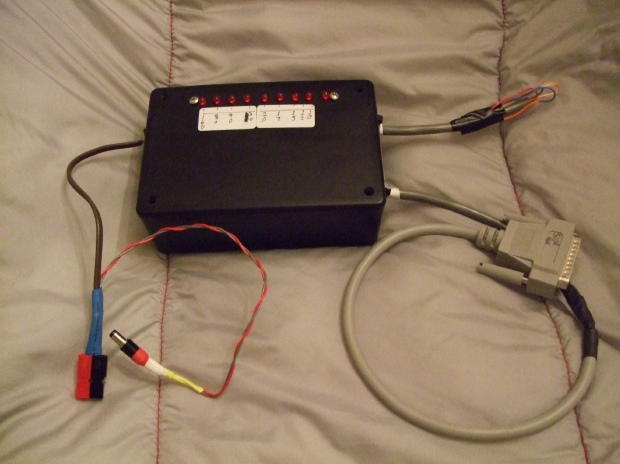
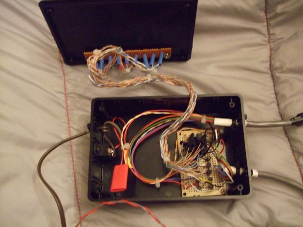
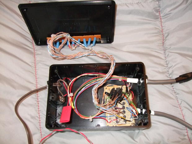
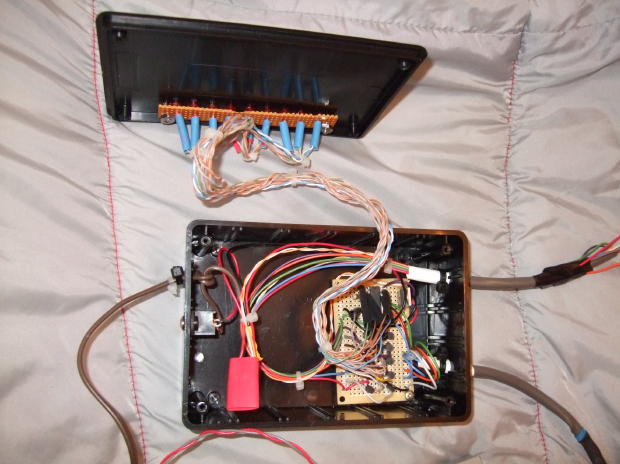
On the top cover are the band indicator lights, connected to the decoder board via a harness made up from Cat-5e twisted pairs. The band data comes in from the source into the CD4028 chip, which drives the N4401 NPN transistors. The transistors will be used as sinking switches to drive the relays as needed.

Band Decoder Insides
Band decoder insides
FinePix F45fd
8/1/2009 5:11:46 PM

Another innards look.

Band decoder insides
FinePix F45fd
8/1/2009 5:12:23 PM

Another look at the innards.

Band decoder insides