|
| SO2R box remote audio switch |
|
|
FinePix F45fd
8/1/2009
5:17:18 PM
|
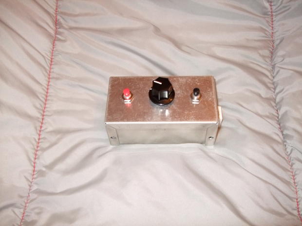
This switch box is set up to switch the audio for the left and right radios. The choices are left radio only, right only, stereo-left in left & right in right, and reversed stereo. The pushbottons are momentary contact switches that allow goinf from stereo to either radio alone. The box is just the right size for placing next to the keyboard when operating. I generally have it paralle the keyboard just above the numeric keypad.
|
|
|
SO2R box remote switch |
|
|
FinePix F45fd
8/1/2009
5:18:50 PM
|
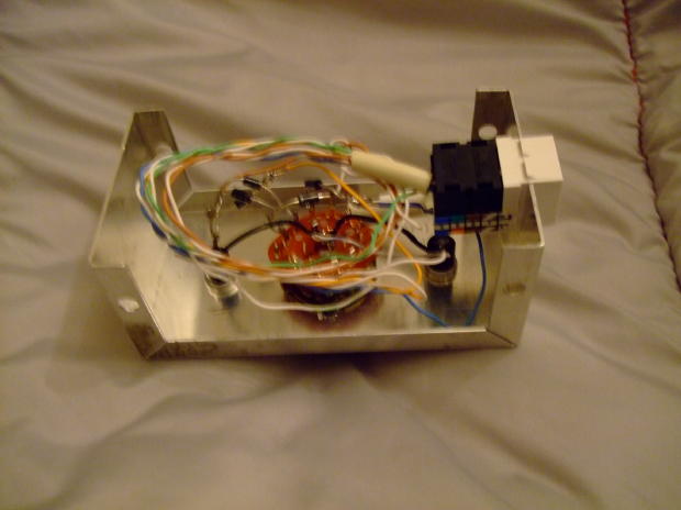
The switch gizzards. The diode matrix is soldered directly to the switch, and a cat5 keystone connector is used. The interface cable is one half of any generic cat5 straight through cable. There is a custom connector on the so2r box side, although in hindsight a cat5 connector would have been a better choice there too.
|
|
 |
|
|
| SO2R box plug panel. |
|
|
FinePix F45fd
8/1/2009
5:20:07 PM
|
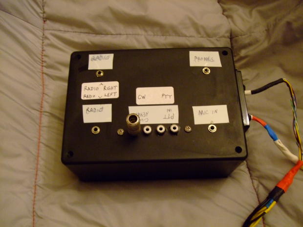
The audio, ptt, CW and Mic all plug in to the switch box here.
|
|
|
SO2R box - Radio side view |
|
|
FinePix F45fd
8/1/2009
5:20:47 PM
|
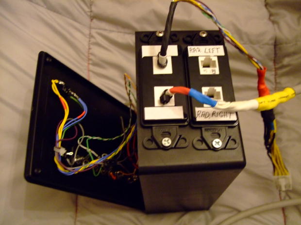
The cable bundles on this side of the box are the radio ins and outs. The two cat5 connectors are for the radio signal interfaces, and are wired identically. They include the CW, PTT, and microphone signals.
The cable bundle with the 8 conductor computer molex connector goes to the remote audio switch. It carries only the relay control voltages - no signals.
The other cable has a DB25 connector, and is the pass along of the band data from the computer - currently only one radio.
The remote switch cable could have been a cat5 connector, but I decided it might be hazardous to use the same connector as the radio signals. The 8 pin connectors are from a computer power cable extension that was cut in half to make both ends of the connection.
The keystone jacks were on hand, as well as the face plates. They cover up the rough holes in the box quite nicely.
|
|
 |
|
|
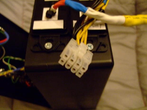
| SO2R box |
|
|
FinePix F45fd
8/1/2009
5:21:30 PM
|
The remote switch connection - a close up of the sor2 box side of the connector.
|
|
|
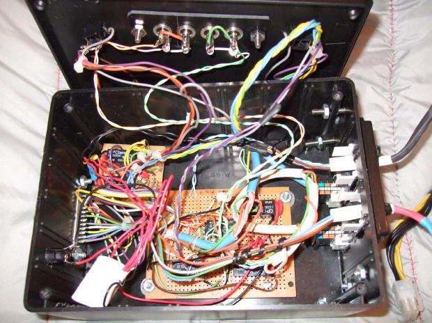
SO2R box - gizzards#1 |
|
|
FinePix F45fd
8/1/2009
5:22:29 PM
|
On the left of the box is the db25 for the input from the computer. I use the LPT port because it simplified the construction. A lot. Power also comes in on the left, and I considered drawing the relay voltages from the computer, but have not done that yet.
|
|
 |
|
|
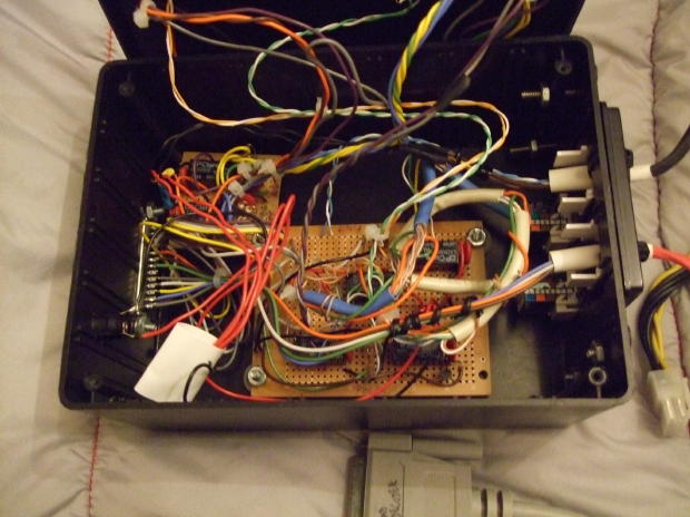
| SO2R gizzards#2 |
|
|
FinePix F45fd
8/1/2009
5:22:59 PM
|
Woooo. Rats nest. Twisted pair pulled from cat5 are used for all jumpers. There are a total of five small signal relays used for the switching.
|
|
|
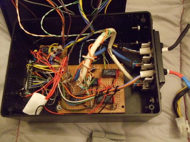
SO2R gizzards#3 |
|
|
FinePix F45fd
8/1/2009
5:23:45 PM
|
The big clunk of white shrink is the fuse. There were a bunch of 1.5A fuses laying about, so I just soldered one in line. It is easy to get to, so if it blows it won't take much longer to fix than using a real socket.
|
|
 |
|