|
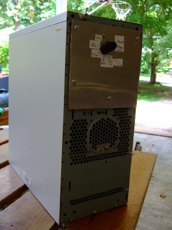
| The W4KAZ version of the NVARC Filter unit |
|
|
The individual NVARC filters were stacked inside this computer case and tied to the front panel switch via a pair of coax jumper to each filter.
It has the five contest bands from 80m-10m, no 160m filter is installed. Needs a better label too. The "custom" front panel was
made by cutting a piece of scrap luan plyboard to size and gluing strips of 5"x7.5" aluminum house flashing to the surface. Given the difficulty
I'm having finding large, CHEAP metal enclosures, this is a possible solution.
5/27/2009
11:03:54 PM
|
|
|
|
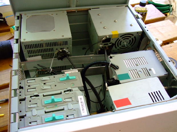
Inside the filter box |
|
|
This case is from a dead Gateway tower, and has a spring loaded top/side panel that pops off for easy access.
Here's a look down from the top. The switch is mounted out of sight in the drive bay. Each filter is in its own power supply enclosure,
and there are six of them. 80 meters required two, per the NVARC examples.
5/27/2009
11:05:15 PM
|
|
|
 |
|
|
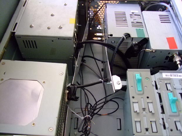
| Inside the filter unit |
|
|
This angle shows the filters from the front of the box towards the rear. The cross braces were cut from aluminum flat stock, and attached in
a rather haphazard manner. The power supply cases fill up the depth of the case, so it enough support to heep things in place
when the box is moved around. The clump of wires in the center are grounds for each filter to the computer case, all tied to a conveient motherboard
mounting stud which accepted a half-inch long 6/32 stainless machine screw.
5/27/2009
11:05:58 PM
|
|
|
|
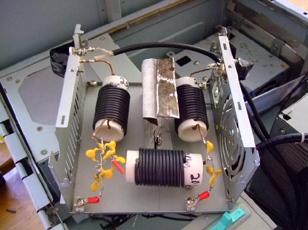
The 20m filter gizzards |
|
|
The NVARC site has better photos, but here's a sample of what the finished filter looks like. The sheild in this one is a bit of scrap from an old pan liberated from a certain kitchen.
Somewhat weathered from sitting out for a couple of years in an unsheltered storage area. One of the kludges I chose in construction was to
simply tack coax jumpers onto the so-239's. Probably less than ideal, but the wattmeter could not detect any drop in
output power. If I decide to ditch the big clunky box, 10 snips with the angle cutters and the filters are liberated.
5/27/2009
11:08:14 PM
|
|
|
 |
|
|
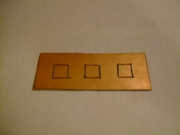
| K4VX circuit board |
|
|
Here's a bit of circuit board mane ready for a single K4VX style filter. The dremel tool was used to
zip a few pads onto a chunk of copper-clad board. Manhatten style pads might be easier, but just as effective.
5/19/2009
3:01:18 AM
|
|
|
|
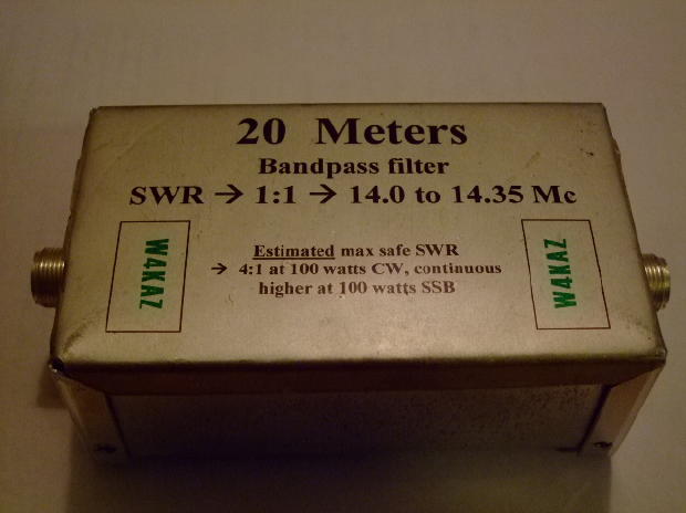
A completed K4VX band pass filter |
|
|
Wooo. A little fancier on the label for these, huh? The label was printed onto clear label stock on an inkjet printer, the given a couple of coats of clear poly lacquer
to keep the print ink from rubbing of when it gets wet. It makes a nice looking label on aluminum. The coat of lacquer is a must.
5/19/2009
2:58:42 AM
|
|
|
 |
|
|
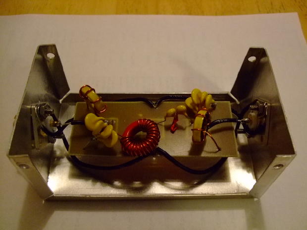
| 20m kidneys and gizzards |
|
|
Here are the guts of the 20m filter. I chose to use the 3KV parts specified by the NVARC project for the last couple of K4VX filters. These ceramic
capacitors have all been testing very close too their printed values. Almost scary how close their values are to the printed values. These
are closer to their nominal values than the 5% silver micas. Here I mixed and matched to get the 500pf and 50pf needed for the 20m filter.
5/19/2009
2:59:11 AM
|
|
|
|
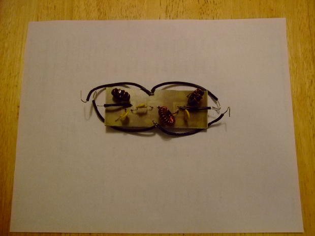
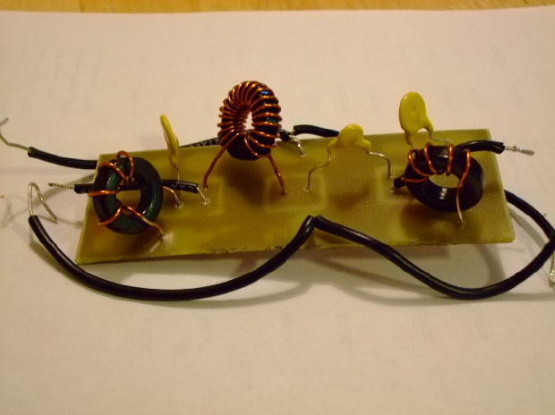
15m K4VX filter |
|
|
A K4VX filter for 15m before installing into its enclosure.
5/19/2009
2:53:50 AM
|
|
|
 |
|
|
| K4VX filter for 15m |
|
|
A closer look at the 15m filter. I used t68-10 cores for 15m and for the series inductor in the 10m filter.
The shunt coils in the 10m filter were air wound, and four turns to four and a half around a pencil seemed to be about right for the job.
Shown here you can see the contortions needed to resonate the 15m shunt coils. The tuning of these two coils was very sensitive to slight
changes in the coil positions, so a lot of careful handling is requred after they are tuned. It makes installation into the enclosure a bit
tedious.
5/19/2009
2:55:48 AM
|
|
|
|