This home brew SO2R controller project follows the “old-n-busted” theory, and is based on the design by N6BV in the ARRL Handbook, as well as some input from K4QPL. In summary, it is built around the use of an LPT port for computer control of the CW, PTT, Radio A/B, and band data. As previously outlined, the LPT port is less expensive and easier to accommodate – even if obsolete. Hence “old-n-busted”. I expect to be able to bridge the gap to USB at some point by adding a K1EL WinKeyer, and the Piexx SO2Rxlat dongle.
The rig control is still accomplished via a serial port for each radio. The LPT parallel port is used for PTT, CW, transmit focus, and band data for one radio. The K2 band data is a separate option not installed in my K2[another void the Piexx SO2Rxlat dongle will solve].
As it stands now the only parts missing for a conversion to USB device control are the WinKeyer and SO2Rxlat devices. Everything else in the SO2R control chain is home brew.
There are several resources available that block diagram the components needed inside the shack for SO2R[e.g.,see DL1IAO, for the W5XD SO2r Box].  For ease of use and construction, the heart of the SO2R box breaks down into four logical units which were built into three separate boxes.
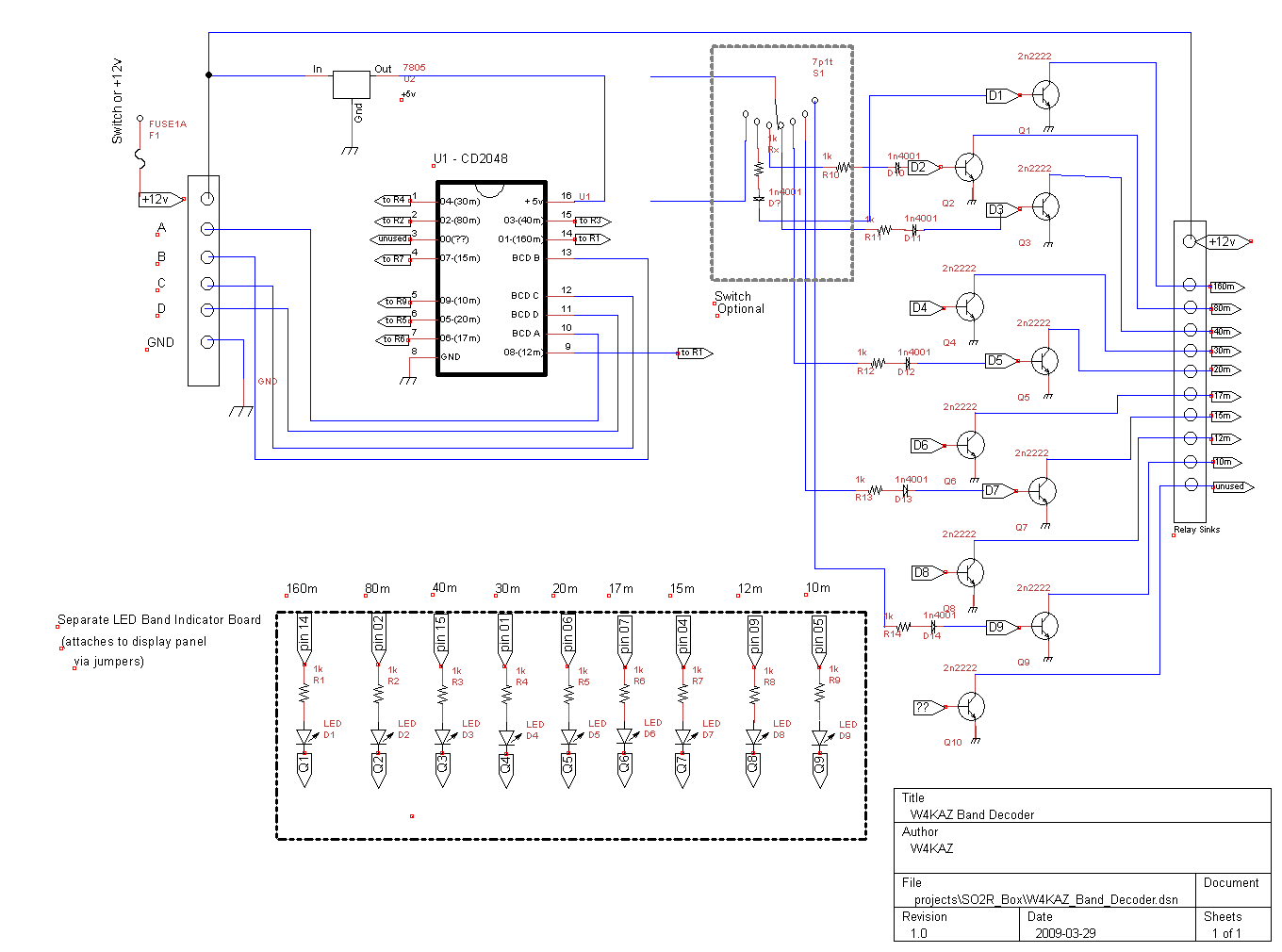
Band Decoder: One of the peripheral boxes will provide automated band switching driven by the logging program[or directly from a radio] by acting as the band decoder. Most logging programs provide band data in the “BCD” format, and Yaesu radios provide that format via their hardware dedicated band data outputs. The binary coded band data make the design of the decoder relatively simple. In hindsight, it seems like a good idea to expand this component’s abilities by using a set of relays to provide for either positive or sinking switching. This is a consideration for driving band pass switches or antenna switches, and is also a design factor for home brewing those components.

The internal view of the band decoder
Band decoder schematic. PNG Image, PDF file
For those looking for an inexpensive band decoder solution, the Unified Microsystems band decoder looks like a real bargain and could easily be incorporated into a home brew design. To build a band decoder, it is probably better to start off with the Unified Micro unit and build the support hardware around it.
Audio Switch: The second is a simple peripheral to the main SO2R box is a simple remote switch. This device itself is simple, yet it really makes the SO2R a lot easier. This device was subdivided into two physical component parts. The actual relay board that switches the audio was built on its own small pc board and mounted within the SO2R box. The user controls are mounted in a small project box. The small box sits just above the keyboard on the desktop.
For my own preferences, it seemed better to have one small “remote” user control box for switching in the heat of battle. The remote has a rotary switch to control the headphone audio, and it can choose either radio individually, stereo with one in each ear, stereo with left and right reversed, or it can be set to have the audio follow the transmit focus. It also has a momentary contact switch for each channel, which can be used in stereo mode to listen to either channel for as long as the switch is depressed. The remote switch control is connected via a Cat-5 cable to the SO2R control box. The control box and its rats nest of wiring can be placed away from the station controls.
Remote: The momentary contact switch feature will soon be enhanced to correct an original construction oversight. Parallel connections for the momentary contact switches will be added to allow using a footswitch. That will provide hands-free audio switching when in stereo mode. That is important, as I need the hands free to type and deal with CW and radio tuning. Hat tip to K4QPL for the idea.
Remote locating allows both the main SO2R box and the band decoder to be located away from the other major components in the station. That highlights the single caveat I experienced – RFI on SSB. After experiencing RFI problems during ARRL SS SSB, both of these units still need some attention paid to choking RF on the interconnects. Re-locating them a bit further from the RF hot spots and coax connections should also help with the RFI. Judicious and liberal use of clamp on RFI chokes seems to abate the problem.
For some reason, the K2 seemed more susceptible to RFI than the Yaesu FT-920. The RFI source there turned out to be on the PTT line. A combination of ferrites and a diode in the PTT line finally tamed that hotspot. Note: in the PTT line, the PTT hot is at the radio’s mike connector, and it really didn’t sink into the thick head right away.

W4KAZ SO2R control box
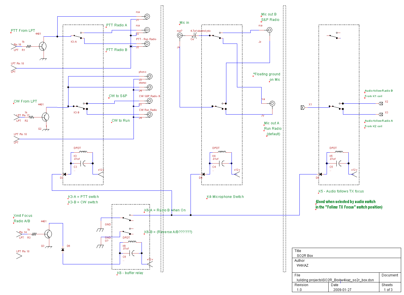
SO2R box schematic PNG Image, PDF file
Audio switching schematic PNG Image, PDF file
SO2R Box: The guts of the system all reside in the main SO2R box. It has inputs for headphone audio from each radio, CW inputs, PTT inputs, and microphone audio inputs. There is also an LPT Db-25 input for connection to the computer. The set up is designed to receive control input from the computer LPT port to drive some of the switching and provide band data.
The main box contains two separate components. Two small perf boards were used to simplify construction. One board contains switching for the headphone audio. The other board handles switching for the CW, PTT, focus control, and microphone audio. The audio is normally switched via the switch remote, but it can also be slaved to follow the logging program’s transmit focus and be controlled from the main SO2R board.
Future Migration to USB:
In order to migrate to a logging computer with USB ports, it should be a minor change to replace the LPT cable with a USB connection via the Piexx SO2Rxlat device. By making the components LPT port compliant, the SO2R capability can also remain backward compatible with an older computer that has no USB support, running Writelog. Just in case the only option is an ancient junker from someones junk bin. The SO2RXlat will also provide band data for both radios via a single LPT DB-25 connector.
Postmortem:
The total cost in parts was not large. The 4401 NPN transistors, relays, connectors, bypass caps and diodes were all generic ‘project part’ items I have been accumulating over the past several years. I have gravitated towards using RCA connectors because of the availability of inexpensive sheilded RCA cables and the low cost of the connectors. The CD2048 IC for the band decoder was a dedicated purchase, and were around $1.98 USD. The amount of time put into construction, the biggest real expense, amounted to about 15 total hours, spread over a long period in several hour long increments. I spent more time debugging the RFI issues.
The RFI is probably partly due to using plastic enclosures, but these enclosures were easy to come by. In hindsight I would add ferrite beads on to all interconnects inside the boxes. The ferrites on the interconnect cables create a bit of additional clutter and impede quick wire pulls. Kludgy.
The remote switch has since been modified to add a jack for an external switch to concentrate both channels on either the left or right radio. This will allow for use of a foot switch and will allow hands-free audio switching.
Leave a Reply