By w4kaz, created on 2023.07.02 at 23:31:36 | last changed on 2023.07.06 at 12:13:30 |
Crazy weather. Check Unique Location. Check. Mediocre Antennas. CHECK! No 10m. Check….. 🙁 Typical Field Day.   Check. see the select photos…..W4KAZ 1B NC 2023 FD photo slide show
Crazy Weather
The days leading up to field day 2023 were filled with rain and prognostications of more to come. While having doubts there would be any chances at having a good chance of operating with the expected lightning, the reservations for the great location had been laid in and paid for. Tropical conditions could have made the trip dicey, but that junk kept on its westerly track to western Carrib.  All of the NC wx junk was spawned by a low pressure system sitting in TN and throwing moisture at us from FL and the gulf coast.  The “bands” of storms flowing through NC peaked midweek, right through travel to the Island.   bleh. Arriving Thursday the wx relented long enough to move vehicle contents indoors. Bands of rain, batches of sunshine alternated ad. infinitum. Lots of time for relaxation. Friday afternoon brought a longer window of almost 3 hours of clear wx for setting up antennas. Then more lightning and rain.
Unique Location
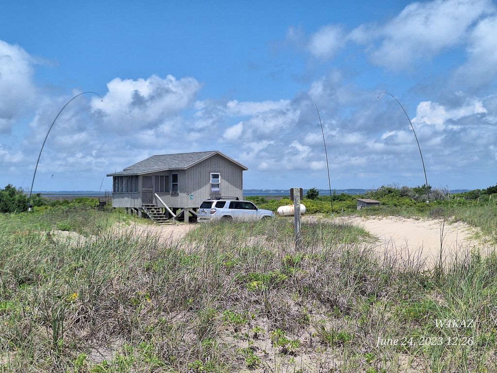
Cape Lookout national park provided a great spot for running a field day operation. The park is a barrier island on the NC coast. Beautiful in its own deserted island sort of way. The wx improved constantly during the four day stay….with the exception of a squall line that that moved slowly through Saturday evening. Operation was shut down for that period, but there was only rain. Great time to catch up on some sleep though.Â
Mediocre Antennas
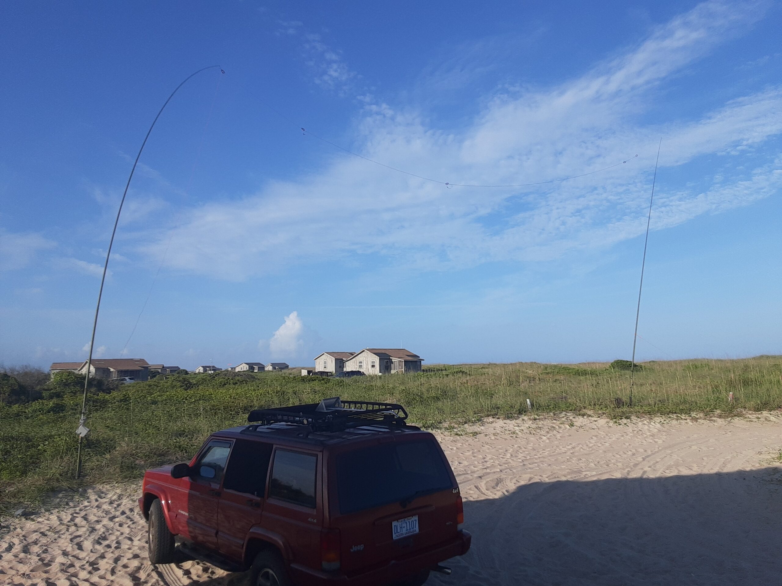
The antenna plan was hampered a bit by having only four of the five masts intended. Something always gets forgotten. Two 40m EFHW antennas were deployed. Both were configured as inverted L’s. The “main” antenna deployed with the horizontal tip pointed North, the second deployed with its tip facing west. The “main” antenna was also manually switchable to being used as an 80m vertical with a K2AV style counterpoise.  The only band that felt loud was 80m. These efhw’s mounted as inv-l’s are a bit compromised on 40m & 20m, both by the configuration and being relatively close to the ground.
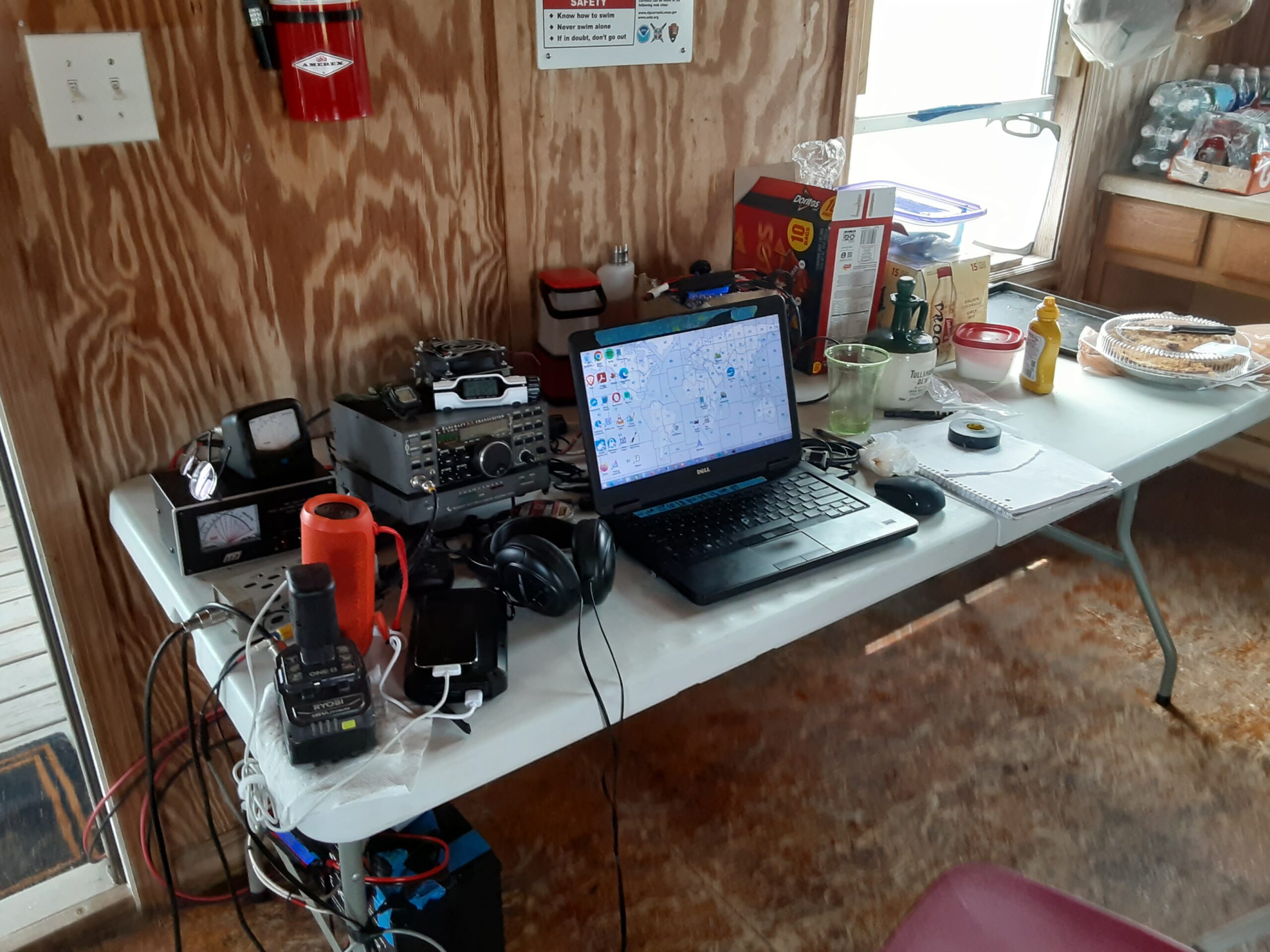
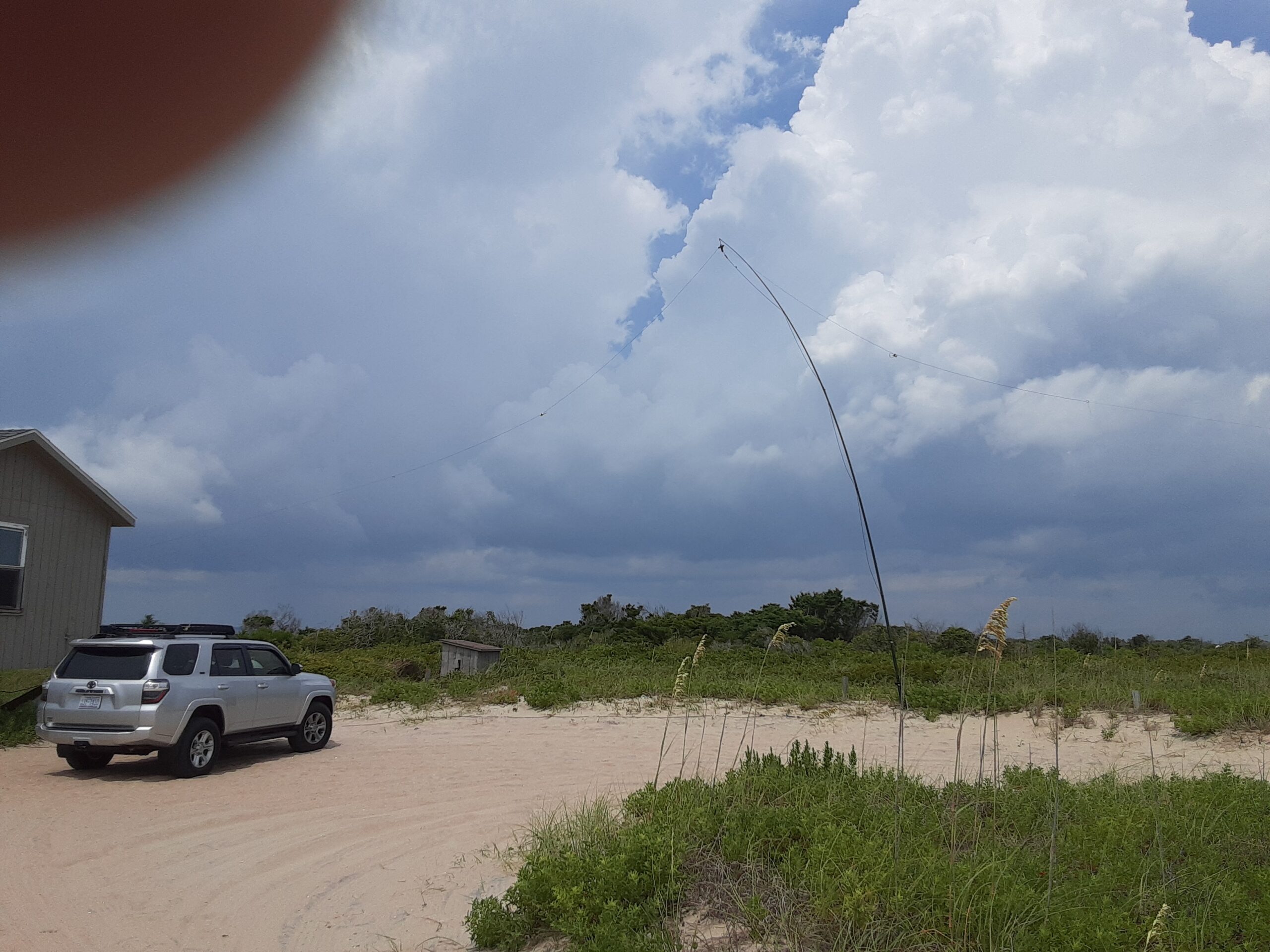
W4KAZ 1B NC, Cape Lookout qth for the FD weekend, All set for FD. The antennas: Left most and center mast hold “main” 40m EFHW/80m base on left and end at center mast. The rightmost mast holds west facing 40m EFHW which slopes toward ground, and is tied off behind cabin.
No 10m
10m was yet again a disappointment. The recent rise in sunspots must be less effective in light of the pole shift and weakening magnetic fields. Radio propagation is probably just a symptom of what might be a much bigger issue. Keeping the band map loaded with packet spots from VA and NC skimmers showed very few spots on 10m at any time I was on the air. 15m was only very slightly better. Perhaps Saturday evening was better.  20m and 40m were the places to be for the most part. 20m was more interesting, and accounted for the bulk of the Qsos logged. The early morning Sunday accounted for the only qsos there, all logged around 0900-1000z.
FD as IOTA Prep
FD antenna choices were made as a test for the upcoming IOTA. The alternate choice was to mount the “main” N/S efhw as described before, but to use a 50m/20m trap dipole as the secondary antenna. This second pair will probably be better for an IOTA situation, with the dipole being a better choice for DX. Alternates/backup antennas are a linked dipole that could be used on any of the individual bands and a set of wire verticals. Also a 15m/10m trap dipole…..just in case.
The Good, the Bad and the Ugly
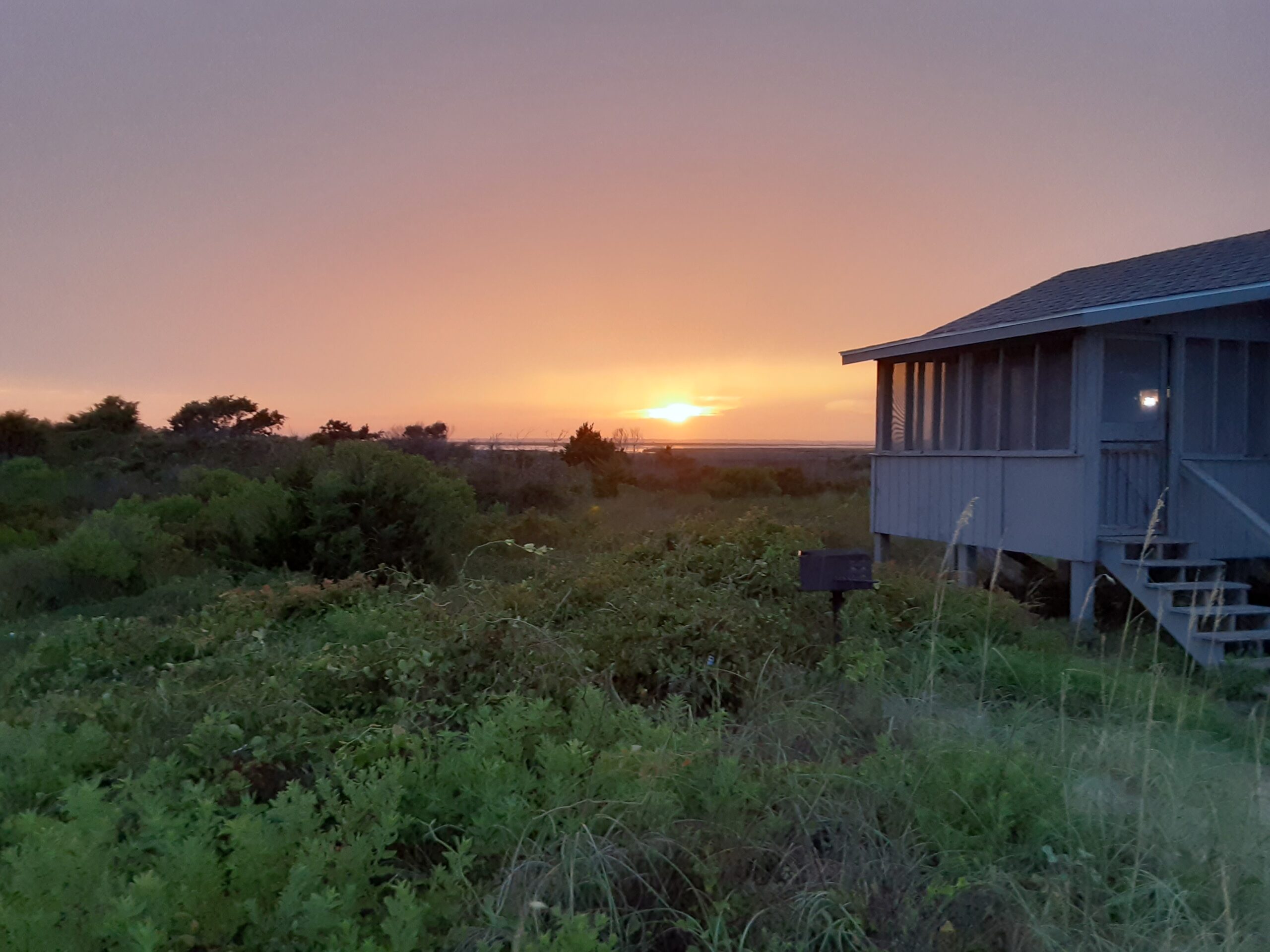
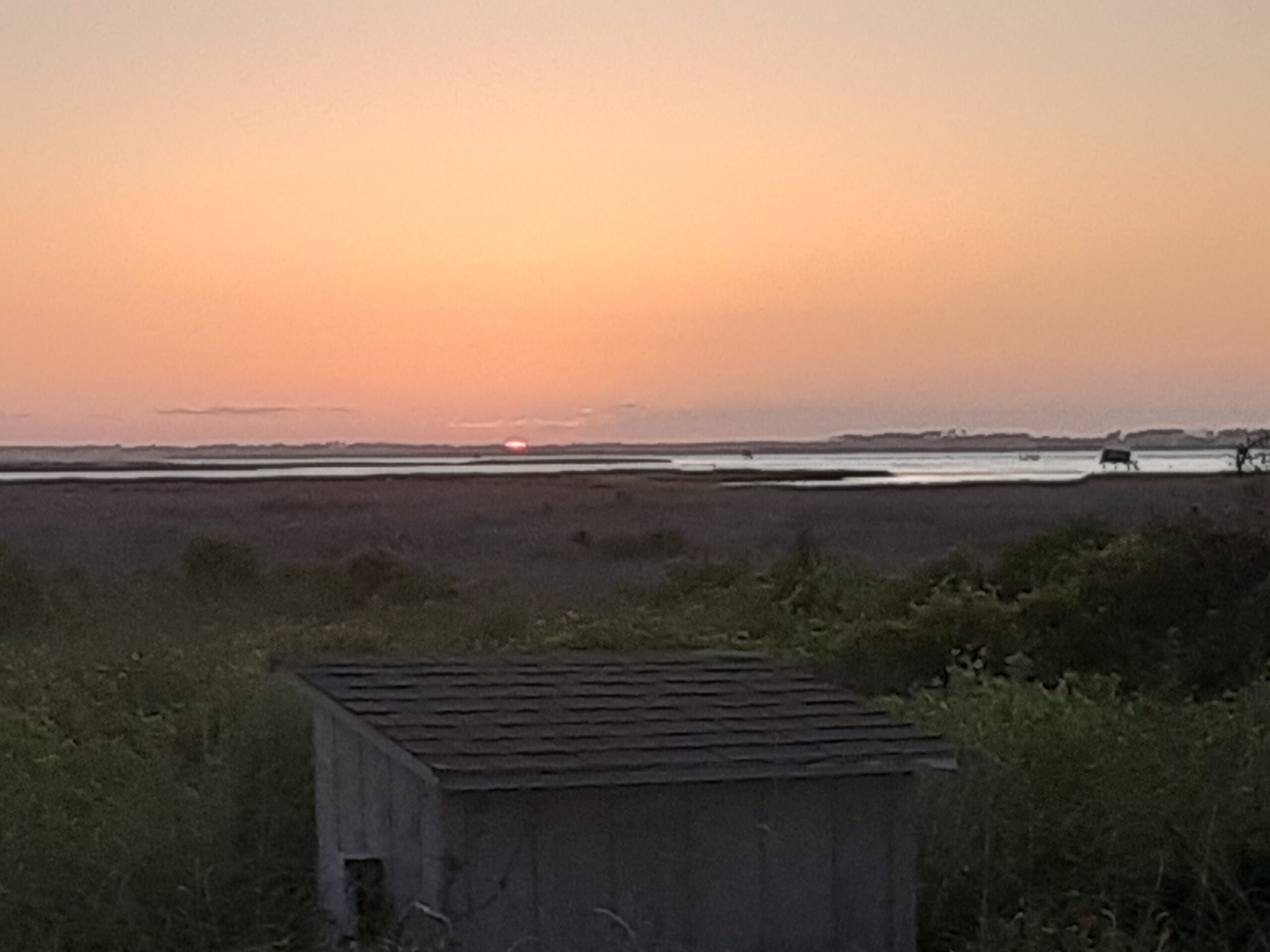
Start with the ugly…..a slow band of squall lines moved in Saturday evening. Fearing more lightning I dropped all the antennas. Being exhausted, I hit the sack to the pitter-patter of another batch of rain, which turned out to be the last of the trip.  The bad…..missed out on the evening which probably cost a lot of qsos. But without the much needed sleep, Sunday would have been a tough slog. 10m and 15m were disappointing. Missed packing one of the bags with some of the kitchen odds-n-ends, so had to improvise. The good…..Morning coffee….two magnificent sunsets on Friday and Sunday. Cigars and whiskey. Moderate temperatures and a nice breeze. Moderate bug levels.
Details Details Details
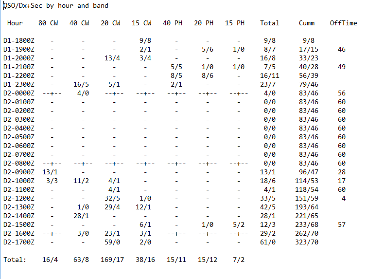
W4KAZ 1B NC 2023 FD breakdown by hour.
Saturday afternoon was S&P combined with wishful thinking about 10m and 15m. Didn’t feel loud enough to run on SSB. Then clouds stacking to the west and a check on the wx radar convinced me to lower antennas prematurely. The squall line was slow, and arrived with more rain. Was exhausted anyway so ditched for the evening. Up at 0800Z and started on 80m to try to capture the available qsos. Took a breakfast break at the not so spectacular sunrise, then alternated between 20m/40m/15m for the rest of the morning. Finished up on 20m with the best single hour. Then a couple of hours of breakdown and packing. Bada bing bada boom. Another FD bites the dust. 320-ish qsos, about
By w4kaz, created on 2022.07.12 at 23:08:10 | last changed on 2023.07.06 at 12:04:47 |
Schedule is set for another adventure to Cape Lookout, NC over the IOTA weekend. The plan for operation is going to be a very relaxed approach, depending on the WX and radio conditions. Activity will be condensed to mostly Saturday, but maybe some POTA calls Friday night or Sunday morning. Probably will have only 40/20/15/10, and forego 80m. Probably not worth the effort to add 80m if 20m stays open into the evening as it did for FD.
UPDATE, 2022/08/29.
End of July WX made the event mostly a bust. Decent WX on Friday afternoon on arrival, so antenna set-up went swiftly. The weather deteriorated as evening came on, so the Antenna supports were lowered. Saturday morning brought clouds and lightning. The weather attempted to clear of for a couple of short windows. The final window was in the mid afternoon, just as radio conditions began to show promise. Lightning soon returned along with a couple of driving rainstorms early Saturday evening.
The QSO total never grew to useful levels, and the na-067 mult was scarce from the w4kaz op. 37 QSOs total, all on SSB.
Photo of antenna mast in down position
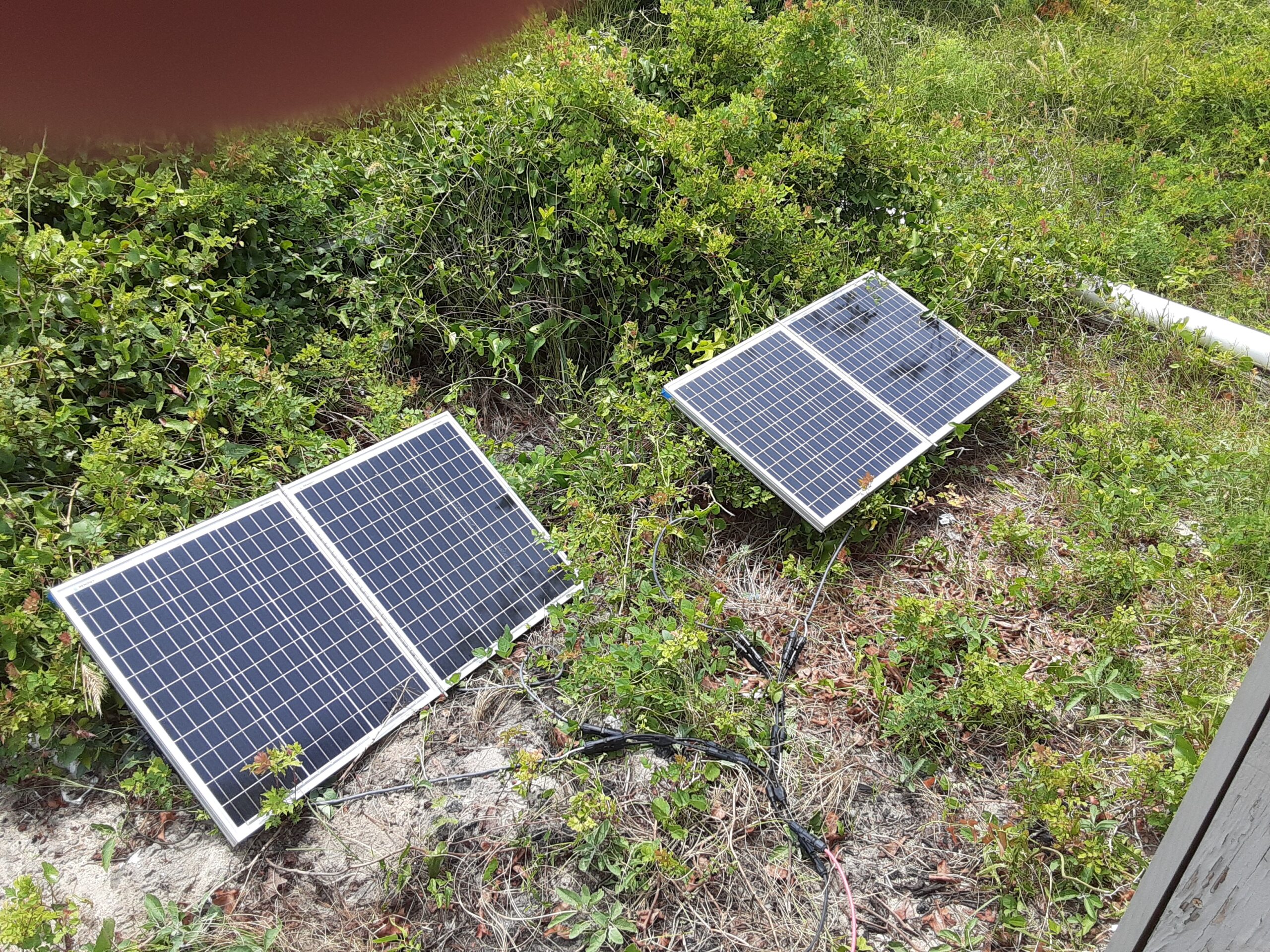
Photo of solar panels for topping off battery.
The 2022 IOTA station. Destined to be under-utilized
Antenna is 40m/20m trap dipole. Intermittent lightning in background not depicted.
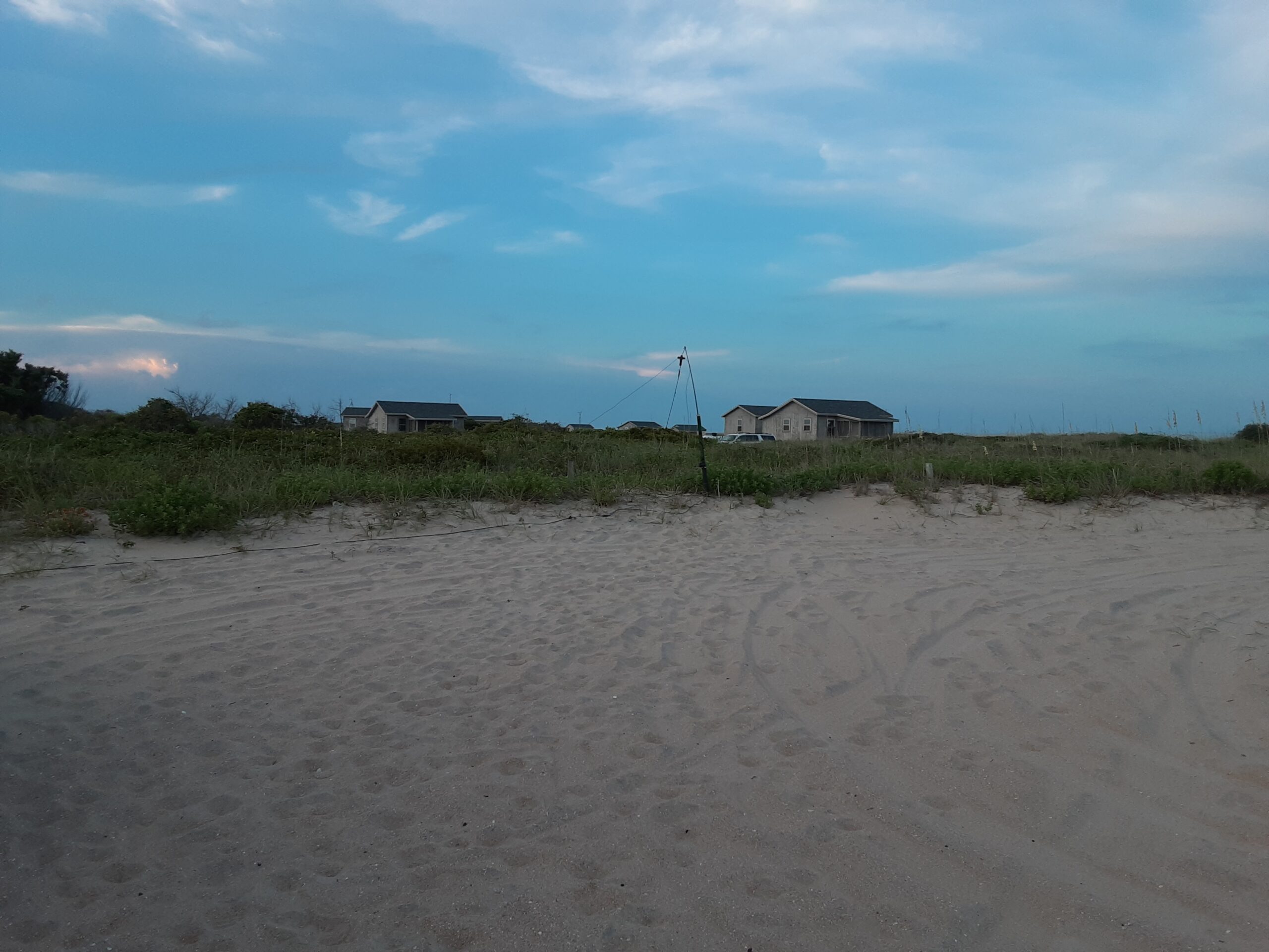
Photo of sunset from the day before operating event. Was hoping for this on event day, but no such luck.
By w4kaz, created on 2022.07.12 at 22:29:01 | last changed on 2022.08.29 at 21:10:49 |
Passed up a chance to operate at the Korn Krib Kontest Klub of N4GU for a pre-planned solo camp out. Hit my favorite campsite again at Carolina Beach State Park. I allowed for an optional POTA run at Fort Fischer, but lazy won out over ambition on that one. Also used the chance to try out a new camping scheme with mixed success.
I landed on the campsite Thursday afternoon, but made a side trip to Kure Beach, then settled in for the evening. Friday morning was used up sleeping late, making gas run, ice run, and brunch run.
The Antenna Adventure
Setting up the station, a K2, went quick enough. The two antennas went up easily using the same masts I had used to test them with at home. An EFHW for 40m/20m and a 10m/15m trap dipole. FAST……as in too fast.  For some strange reason the EFHW is not tuning………hmmmmmmm. MAYBE omitting the chokes at the feedpoint are the problem. duh-OH!
The antenna still required a bit of tweaking.  “Strange…it worked just fine at home…?” I did waste about 75 minutes screwing around before figuring out the chokes were not installed. After that mistake was resolved I tested out the 80m “variation” that uses the EFHW vertical as a qtr wave on 80m. That is set up as a separate feed point that attaches to the EFHW via a jumper and a swap of coax. With the EFHW working, the 80m variation was actually as trivial as it should have been.
Since band switching 80/40/20 required several manual adjustments, I made a cheat sheet/check list for the tired-and-groggy hours.
Field Day Summary
The weather overnight had been cool(for late June at NC coast), and I woke up feeling hopeful. Never caught any decent propagation on either 10m or 15m, having ZERO qsos on 10m and only 26 on 15m. 80m was so slow I chose going to bed rather than stick it out. With 20m staying open, the stronger stations stayed there longer. Getting viable runs was difficult, outside of a good stretch on 40m abt 6pm, and a decent run Sunday late in the event.
The Dirty Truth
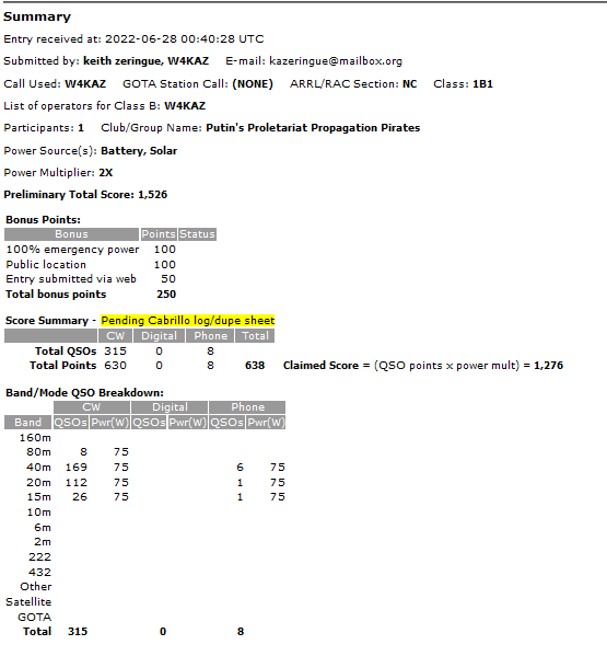
2022 FD w4kaz 1B nc score
The Setup and Station
I ran the Elecraft K2 this year at 75 watts, expecting to put in more operating time overnight than during daylight and wanting to stretch the battery. At some point I decided to power the radio from the main battery, and use a smaller backup battery for computer peripherals. This seemed to cause no problems, and helped keep the voltage up on the radio. In direct sun the solar panels provided about 9-10 amps continuous to an MPPT charger. The panels only got direct sun for about 3 hours though and were only providing 4 amps or less for most of the daytime. The battery finished up at about 75%, so the solar assist helped.
The base station setup for 2022 FD w/W4KAZ
Saturday
WX Saturday was fabulous for late June at Kure Beach, NC. Cool breeze picked up right about 1800Z. Conditions seemed mixed, and activity seemed down. Not enough persistence in getting a run going despite seeing decent spot numbers on RBN. Operating was a lot of S&P and band hopping. 20m was open late and 80m action never seemed to pick up in the early evening. Eventually pulled plug for the evening before midnight.
I decided to operate mostly CW to keep the noise down in the campground. Not needed during daylight, but decided to respect quiet hours in park. That plan was almost blown up by forgetting headphones. So I used a pair of earbuds that usually ride shotgun with the computer. I had a second set of buds, but audio was too low a level in those. Could have made an emergency run to a local wally-mart, but decided to make do.
Sunday
Got on the air again at 1000Z, and had one of my more consistent runs on 40m as the daytime crowd got back on the air. Took a break after a couple of hours to scarf a hasty breakfast, then some more butt-on-bench. The shack was a screen tent that was in full sun for the hours of 1530 to about 1700, so the battery fan helped a lot then. Sunday WX was also good, but slightly warmer than Saturday. The only decent 20m run spanned about 50 minutes during the last hours of the event.
Photo of screen tent shack and additional shade.
The shack was back into full shade by the end of the event. After a short break for a late lunch, the station was torn down and packed into a single tote, with some notes taken on items missing/needed. Everything to be re-used for IOTA again at end of July. Copies of log files made. Then a leisurely dis-assembly of antennas and parts of camp. I kept the screen tent up for packing on Monday morning.
The far side of camp – solar panels, base of 40m EFHW, and gear storage. Note stump, the gremlins got the tree that previously shaded this site over noon hours.
Success!
No major problems, injuries, issues. Great weather, plenty of sleep, lots of cigar time, and a chance to relax. Always learn something, and this time learned a pack list is never good enough to catch everything. And even with everything packed, finding it when needed is a problem. Still hunting a set of earbuds that went MIA.
Notes: Compass, headphones/mic spares, !5v usb batt packs!, USB adapters. vehicle storage organizer. Always double check assembly of complex system when rushing. KAT100 troubleshooting required.
[edited for links and notes, 2023/07/15] The original trap dipoles were constructed using coils and caps. Using Rg-58 for the coax style trap dipoles was rejected because of the weight and size of rg-58 coax traps. Using RG-58 defeated the primary goal of making the antenna as light weight as possible.
Somewhere I picked up the notion of using rg-174 or rg-316 type mini coax to make the traps. It looks like the voltage ratings on the rg-174 is higher(1100v rms), so that was chosen for the first experiments. If luck holds out, the tiny coax will be sufficient for use on the dipole traps for a full 100w CW. Using the smaller lighter mini coax will allow for lightweight construction from easily available materials that can be easily supported using telescoping fiberglass masts like those available from Spiderbeam, MFJ, or Jackite. i.e., perfect for portable, field day, rover QSO parties, or POTA/SOTA.
The trap calculator program hosted by KC1KCCgave me some starting numbers to work with, and actual trap measurements came out quite close to the calculated values. [alternate calculator at K7MEM]  The traps are built with the coax coils wound reasonably tight to the form, and the coils were taped down with electrical tape prior to taking measurements. These are all wound on small sections of the same sort of plumbing drain tailpieces that are 1.5″ od (38mm od). (e.g., in the US available from Lowes or any hardware store selling plumbing supplies.) The table below are of traps as built and tested with the nanovna.
frequency
turns rg-174
27.7
3.33
20.66
4.33
13.75
6.1
6.75
10.3 [calculated]
Update, 2024-04-04
Received a new 1 inch o.d.(~25mm) form material that is lighter. testing.
Freq———–# turns calculated——#turns actual——- 27.7Mhz—>5 turns (approx)—–> 5 turns, 24.8Mhz(use 4.5?)
20.66Mhz–> 6.25 turns————> 6.25 turns, 19.65Mhz(use 6)
13.75Mhz—> 8.75 turns ——–> 9 turns, 13.5Mhz & 13.7Mhz
6.75Mhz—-> 16.33 turns END 2024-04-04 Update
Test Antennas:
The test antennas were built for the CW segments of each band. With the best SWR centered on the xx.070 area it will probably give enough coverage for both CW and SSB operation without a tuner. An 80m/40m version will require tails for 80m adjustments.
Testing of two antennas was done before the May 2022 CQ WPX CW contest. The 20m/15m version tuned easily….after I figured out I was working on that instead of the 10m antenna. Read those labels, because at least I had them labeled properly when they were built several weeks earlier. The 10m/15m version also tuned easily.
[aside: the 15m/20m trap is now in service as the skimmer station antenna, after a recent storm broke the 160m inv-l]
Although I missed the WPX contest, I soon got a chance to do antenna testing at 100w levels.  Both antennas handled the power easily with no signs of SWR rise. Both were tested at 10 seconds, 30 seconds, 60 seconds and five minutes of CW key-down.
Hoping for good conditions in FD to allow testing of the 10m/15m version. Sunspots, do your thing!
[2023-07-15 additional notes] The coax traps began showing swr problems on 10m after a few months in the weather. Expecting this to be a problem with water intrusion. testing the use of WeldBond glue as a sealant. [alternative….Elmers ProBond] Also testing the adhesive as a sort of q-dope to seal the coils on the form.
By w4kaz, created on 2021.07.10 at 16:29:23 | last changed on 2021.10.18 at 11:37:50 |
Very part-time and casual Field Day this year, mostly a vacation break at Cape Lookout National Seashore with a couple of tag-along non-ham guests. Set up of the station late Friday afternoon was pretty low key. Not a lot of work involved. Planting two auger bases into the sand and mounting two telescoping masts was very simple. The 40m EFHW went up soon after. A folded counterpoise radial for 80m was laid out along with a separate feed point box for converting the antenna into an 80m quarter wave vertical as needed. The station was fully set up and tested Friday evening.
Station
The FT-891 was used along with an MFJ external tuner, mostly for its ability to double as an antenna switch. Computer logging with N1MM was tested and ready. Very simple. The most complicated part was configuring the sound card settings to use the computer for voice keying. The station was completely battery powered, and the battery was supplemented wit 200w of solar panels. Everything tested and working early Friday evening. Just in time for bacon wrapped shrimp kabobs, supplied by tag-along companions. And the obligatory whiskey and cigar break.
Saturday, time to welcome Murphy to the party
Count on Murphy to make an appearance RIGHT at the start of FD event. Somewhere along the way the logging computer went to sleep causing N1MM to delete the logging files along with all of the settings and drivers for communicating with the radio.[The *.s3db file disappeared, although that was determined a few days later.] The first hour was blown trying to re-connect/configure N1MM with zero success. So it was time to ditch N1MM in favor of using Writelog. The only reason N1MM had been set up was that it could connect to the FT-891, which I cannot get set up in Writelog. Switching out to the Elecraft K2 backup radio was considered, but instead decided to forego computer-to-radio comms and do band changes manually. That was certain to have caused some log errors, but it was simpler than switching radios while angry/disgusted/tired. My low opinion of N1MM logging program was reinforced.
It turns out there was no burning reason to rush. Saturday conditions were none too interesting, with little activity on 15m and 10m. The relatively weak antenna for 15/10 did not help that situation. Or maybe everyone has switched to digital modes. It also became apparent from RBN spots that the antenna orientation was heavily favoring Europe instead of the US on 15m and 20m. So a bit of SSB S&P on 20 and 40. Also took the opportunity to fiddle with the antenna by removing the jumper to make it a 20m EFHW. This worked better for 20m in the short time on the air before dinner.
Being mostly casual, the folks that tagged along for vacation time pulled out the night’s meal. That was later accompanied by a bit of whiskey and cigar time. When the tag-alongs decided to turn in for the night it was time to get back to radio for a bit around 0400Z. Being 80m time, a foray out among the bloodthirsty nighttime island fauna was required to make the manual switch from 40m EFHW to 80m vertical. A nice hour on 80m proved the function on that band. Pretty good for a last minute kludge idea. In bed for the night by 0500Z.
Day 2 – Sunday
After a shift on breakfast duty it was back on the air at 1015Z. Worked a few more on 80m before switching the antenna back to 40m EFHW configuration. Then it was a CW run on 20m, to 40m, back to 20m for a good hour. Did a lot of band hopping after the 20m run through 1630Z and called it quits early. As always, tearing down the station and antennas went really quickly. Plenty of time to enjoy the afternoon. The FD log ended with 250 Qso’s – 25 SSB and 200 CW.
CALO wx
The weather over the entire weekend was really nice. Most of the weekend had a cool ocean breeze blowing, instead of the more normal southwest blow. Skies were overcast the first two days, but began clearing Saturday. Sunday evening produced a clear sky and a flowing Milky Way which was followed by a later moonrise just past full moon. It is interesting how brightly lit a desert island becomes under a full moon.
The sand buggy looking at the 40mEFHW feedpoint. And a nice Sunday afternoon sunset.
By w4kaz, created on 2021.06.09 at 08:41:17 | last changed on 2024.04.21 at 12:30:54 |
Wazzap wit dat?
Reality sets in
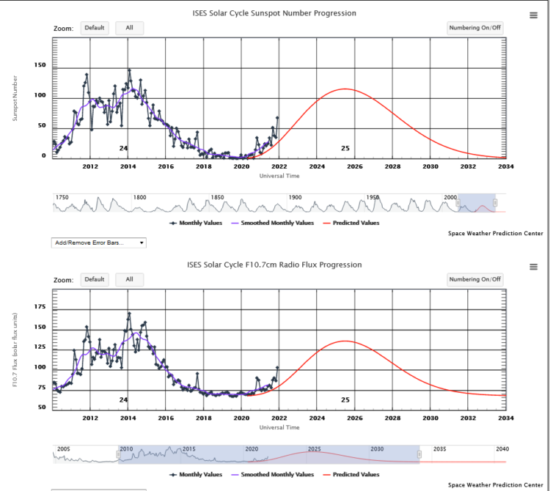
2021_08_21_> Would be really nice to see solar flux improve, but sunspot numbers continue to be/trend mediocre. Either the predicted time scale is going to be longer or the magnitudes of activity lower. Maybe both?  Peak at ssn 60? That would be sad. The optimistic projections would be nice to see again, but I expect to be long dead before that happens.  SSN today at 25. Based on today’s reality, it time to repair the 80m antenna and that 15m/10m project is deprecated.
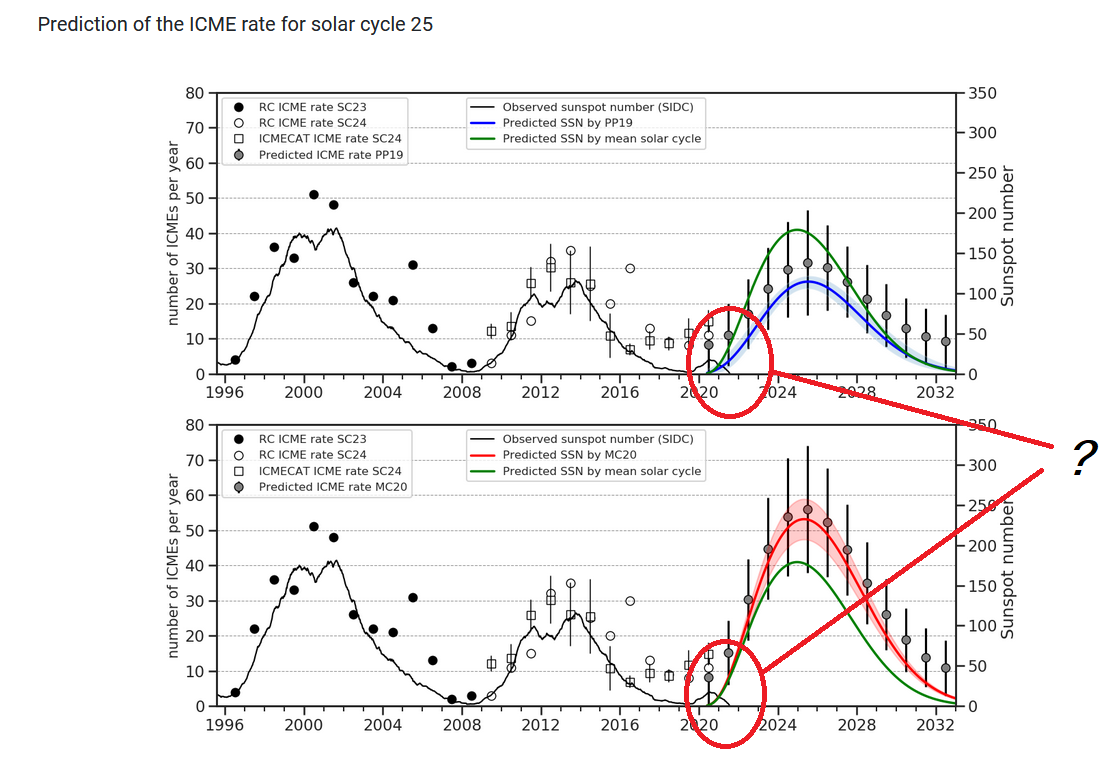
2021_12_26_> What a difference a few months make. Too bad this didn’t show up in the week before the 10m contest. Beginning to think there may be a bigger cycle than I would have ever expected. A few more months of this would make the high bands worth experimenting. Was expecting peaks well below 100ssn….hmmm. From the helioforecast.space site, [current graphic link].
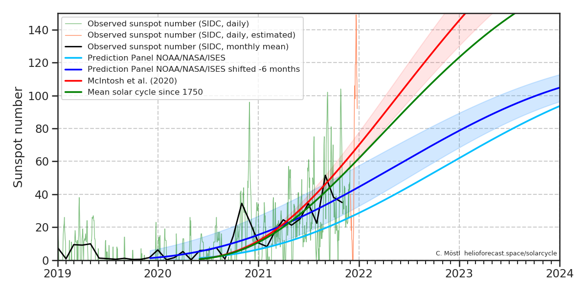
ssn graph, dec 2021….Didn’t ever expect to see ssn over 140 this cycle, or even much over 80.
and:
2022_01_04: This last graph shows the current cycle is ahead of the modest predictions that I thought were over-optimistic. The spike to 140+ SSN in mid December seems more like a much stronger cycle than the last, since the cycles usually ramp up quickly once they begin. That will make fun high bands again, but given the wide range of predictions that missed, even the folks doing this full time might be scratching their heads. Fun stuff. Peaks above 200 ssn? Hoooooweeeeee! 2023 might be the best radio condx I’ll ever live to see again. link: https://www.swpc.noaa.gov/products/solar-cycle-progression
2022_03_30: Well the SSN just keeps a-climbing. Flux movin-on-up. Curve in numbers is still much sooner, steeper, and stronger than anything I expected, and better than the middlin’ prediction that I thought would be a best case.  The last hurrah. Sweeeeet. Now I’m just hoping the polar flip and mini-nova catastrophe sorts are wrong. 🙂 🙂 🙂
2022_07_23: Semi-related, found a really cool RBN mapping site. Check out the work of HA8TKS. Good format, centers an azimuthal projection on the searched call sign with lots of options.
By w4kaz, created on 2021.06.02 at 22:40:38 | last changed on 2024.12.03 at 21:27:52 |
Very casual
The wpx operation was very casual. I spent a lot of the time just tuning around the bands listening. The beginning of a CW contest are always too fast paced for my mediocre CW skills, and taking a mental picture of band conditions was more fun. The bands sounded “brighter” than at any time in the past couple of years.
As a quick-n-dirty mod, I used a second feedpoint to attach the efhw to an 80m folded counterpoise. This is to allow 80m operation by shifting the feedline and using a jumper to bypass the transformer. \/expanded description below\/ This gave the antenna resonance on 3.625Mhz. To drop the resonance into the CW segment I wound a 6 turn coil on a 1.25 inch form. That is inserted at the bypass jumper with faston connectors. To raise the resonance to somewhere near 3.8Mhz a 3kv capacitance of about 500pf does the trick. 80m was good-to-go.
Dirty Tricks Department
So as luck would have it, the good band conditions made testing on 80m less useful than I hoped. 20m was open until at least local midnight (0400Z), and probably was open to somewhere all night. On Friday night few ops moved down as far as 80m with 20m and 40m providing a bottomless pit. It did allow for gathering some info from the RBN spots, which look like either the band was open in famous fashion, or the EfHW was doing a decent job. Maybe a bit of both, as the 80m spots looked pretty good, as well as showing up on some skimmers not normally hit with permanent inv-vee.
The antenna was also able to work most of the stations heard on 10m. That’s a change over the few other recent outings. 15m was a bit of a mixed bag. 20m responses were comparable to other experience with dipoles. 40m seemed unusually good, but it may be more due to the very quiet sounding band conditions. On Sunday a short 40m run coincided with the band opening to Europe, and it is shown in the RN spots. The RBN spots started out as US only. By the end of the 60 minute run there were several EU RBN stations showing 20-30db SNR, and a slow growth in calls from EU stations. Too bad the contest was at its end.
The 80m Inverted-L Mod
The first attempt to use on 80m, the transformer was shorted out of the circuit and the radial attached to the ground lug. This did not work as expected, and more testing is needed, The first thought is the EFHW 120pf capacitor to ground needs to be removed from the circuit for the vertical. The quick field expedient kludge was to move the coax to a feed point not sharing ground with the EFHW box. The first test used a single radial cut for 80m. In that configuration the antenna resonated a bit below the 80m CW band segment. Resonance could be shifted upwards by inserting a series capacitance at the base of the driven element. SWR was very favorable at each resonance point chosen with about 150 to 200 kc of 2:1 bandwidth.
A second option was tested, using a folded counterpoise instead of the single full length radial. In this configuration resonance was at about 3.625Mc. A 6 turn coil inserted in series in the driven element dropped resonance to 3.54Mc, and capacitors can be used similarly to raise resonance to upper SSB band segments. In this configuration the best SWR was about 1.8:1, and bandwidth more limited. Easily stretched moderately with an antenna tuner.
The folded counterpoise version was used in the contest with great success. This is going to require a lot of testing to decide if either version is a better 80m performer. For my purposes, the FCP version is compact and easy to set up, so it will be the one used.
Potential next project: using relays to allow remote switching, both for the transformer taps when in EFHW mode, and for switching components needed to operate as a standard vertical. Hmmmmmm
????photos coming 2021-07???????
Conclusions
The kludgy fix for adding 80m was an outstanding low effort method for stretching the single driven wire to use on another band. The cost is the time used adding the FCP radial on deployment and later some manual band switching while operating. It would not take a lot of effort to add a few relays to allow remote switching – a possible future project. This EFHW would make an outstanding option for quick deployment by folks stuck in enemy territory where permanent antennas run up against tyrannical HOA rules. The whole thing can be deployed or removed easily in less than 15 minutes with a bit of planning and practice.
Having a tapped transformer allows a very good match on each of the five main bands of interest in contesting. I think using the 80m option using a folded counterpoise and 40m EFHW driven element as an inverted-L vertical the seems to be at least comparable to the version with the loading coil and 80m tail extension. It is easy to deploy and switch, and inserting a small coil at the base was easier than tuning the 80m loaded EFHW. An 80m FCP is 32 feet long, so it is fairly compact also.
Adding a linked in tail to the 20m/30m EFHW turned out to be about as easy as you might expect. The 40m EFHW was tuned for 7.100. The other bands could be easily matched by selecting the best match via moving the transformer tap.Â
The links at 20m and 30m will allow a lot of versatility at the cost of lowering the antenna to connect or disconnect the links. Likewise with the transformer taps. So a bit of footwork is the tradeoff for multi-banding. But its not just the band changes. Judicious configuration choices allow the possibility of multiple choices of radiation patterns.
BAND
TAP
Best SWR
SWR range to expect
40m
8.5:1
7.1(1:1)
Entire band, (1.3–>1.6)
30m(j)
8.5:1
10.25(1.6:1)
Entire band, 1.6:1 with wire drooping
30m(j)
8.5:1
10.1(1.3)
Entire band, 1.3:1 with wire pulled taut
30m(j)
7.5:1
10.3(1.4)
Alternate tap,1.4:1 with wire pulled taut
20m(40m-tail)
6.5:1
14(1.4)
Entire band 1.4–>1.6)
20m(no 30m/40m tails)
8.5:1
14.025(1.4)
Entire band favoring CW section
15m(40m tail)
4.5:1
21(1.1)
Entire band 1.1–>1.8
15m(j)
4.5:1
21.010(1.4)
Entire band under 2:1(wire drooping)
15m(j)
4.5:1
21.010(1.0)
Entire band flat with wire pulled taut
10m(40m tail)
6.5:1
28.0-29
Entire band with tap 3 , 2 or 1
10m
6.5:1
28.000-29.25
28.00 thru 28.800 under 2:1(swr 1.2:1 on CW)
10m
8.5:1
28.00(1.4)
28.00 thru 28.75 < 2:1(swr 1.4:1 on CW)
*note1: “40m tail” implies both 40m and 30m links are attached, other settings are for the 20m/10m as 20m efhw or 30m/15m as 30m efhw.
note2: The transformer taps are numbered 1-5, where tap 1=4.5:1, 2=5.5:1, 3=6.5:1, 4=7.5:1, and tap 5=8.5:1 turns ratios. corresponding impedance values would be 1013, 1513, 2113, 2813, and 3613 ohms.
note3: -right click and “view image” to see full size images below
Model Radiation patterns-10m
For the 10m images above, on the left is the modeled current and radiation patterns for the 40m EFHW when used on 10m. The right is the current and radiation pattern for the 20m EFHW used on 10m. Switching requires lowering the antenna to either detach or reattach the link at 20m.
Given the lengths of the wire using a 30 foot(~9 meter) support, either configuration will have a considerable vertical component. The 40m version will add a substantial horizontal component. The vertical components will mimic the horizontal patterns to some extent. But the patterns will likely favor different directions. The differences will surely be modest – maybe enough to be worth testing as options. If nothing else, it may help reduce QRN in some circumstances.
Radiation patterns-20m
For 20m, the radiation patterns might actually be more interesting. The full wave version(from 40m configuration) will present a compressed combination of horizontal and vertical components. The half wave version(20m) configured with most of the antenna vertical will have a mostly vertical component with the 30ft/9m support. This may be a fun experiment in a field day operation. maybe worth the effort of switching the links
On a whim I decided to wind a transformer using two FT-140-43 cores. I went with the same 2:1 ratio as the first transformer. SWR testing using this second version showed that all transformers are not equal. The SWR readings taken using the new transformer with the antenna wire as it was trimmed with the larger transformer did not have similar results. It turns out the new transformer would require re-trimming the wire lengths to bring the 40m band into the same SWR curve. Since I had the 80m coil&tail attached using .250 quick connects, it was easy to add wire. Doing that allowed bringing 15m and 10m to good matches. 20m also found a sweet spot but only on the 6.5:1 tap.
New Version?
Without re-tuning the wire no good matches were obtainable on 40m. Instead of making any permanent changes to the working 40m loaded antenna/transformer combo I am making a different wire based on a 30m wire length. It will include a quick connect to allow the antenna to cover 20m by detaching the section of wire beyond the ~34 foot 20m wire length. That will provide an antenna capable of 30m/20m/15m/10m. This may become a simple way to add a permanent 30m antenna in the w4kaz antenna farm.Â
Maybe I get ambitious and add a second link to include 17m, just for grins. Does an easy tune 30m/20m/17m/15m/10m antenna sound good? One could just as easily add quick links for each band. Using the antenna as a full wave on the 2nd harmonic provides radiation patterns that might be more useful, but either choice provides a method to cover each band. The initial lost opportunity cost is the need for the transformer. For quick and dirty field construction a simple wire dipole or vertical would still be easiest – but mostly monoband, as fan dipoles can sometimes be difficult to tune.
Future ideas
Thinking about trying a different twist on using the FT-140-43 size cores by pasting three of them together for a transformer, and trying the transformers out with 3:1 turns ratios. I have enough of the FT-140 size on hand to do this but used my last two of the FT-240 size. My first test antenna seems to be a success, so it just need to be put on the air some to get an idea of how it fits in. It is always good to have the option available.
20m/30m Constructed and Trimmed
Using the transformer built from a pair of ft-140-43 toroids sandwiched together, an antenna for 20m/10m is now built. It includes a simple wire tail that can be attached as a link to extend for use on 30m/15m. It should be a simple matter to prepare a wire for adding 40m use. With the 40m wire 15m should be use-able with two configurations, either 30m or 40m. If 15m is open that might add some interesting changes in radiation pattern when switching from a full wave to a 3/2 wave. May as well add a jumper for 17m too(later-much later).Â
TAP Cheat Sheet, 30m/20m/15m/10m
Taps 20m/30m linked EFHW (jumper to attach 30m/15m)
BAND
TAP
Best SWR
 SWR range to expect
30m(j)
8.5:1
10.25(1.6:1)
Entire band, 1.6:1 with wire drooping
30m(j)
8.5:1
10.1(1.3)
Entire band, 1.3:1 with wire pulled taut
30m(j)
7.5:1
10.3(1.4)
Alternate tap,1.4:1 with wire pulled taut
20m
8.5:1
14.025(1.4)
Entire band favoring CW section
15m(j)
4.5:1
21.010(1.4)
Entire band under 2:1(wire drooping)
15m(j)
4.5:1
21.010(1.0)
Entire band flat with wire pulled taut
10m
6.5:1
28.000-29.25
28.00 thru 28.800 under 2:1(swr 1.2:1 on CW)
10m
8.5:1
28.00(1.4)
28.00 thru 28.75 < 2:1(swr 1.4:1 on CW)
*(j)= jumper attached for 30m/15m
Other ideas and observations
LINKING – Thinking about creating a “linked EFHW” out of curiosity. If 10m were reliably open I would pursue the idea seriously. The different patterns of radiation going from 1/2, fullwave, 3/2, 2xfullwave would be fun to work through.
Using taps on the transformer —-After testing with two different tapped transformers, using the taps makes it simple to obtain a good match. More on the air testing is needed, but at this point trying to obtain good matches using a single transformer ratio seems futile.
Different cores = different wire With both transformers I found that the length of wire needed was unique to each configuration. The lesson is to build the transformer and tune the wire to the actual transformer being used. The ft-240-43 transformer pair would not match the wire cut for the ft-140-43 transformer pair. Need to build more transformers to see if a pair of identically built transformers(size and number) will both match the same wire. Best guess is that will work. But don’t expect transformers with different toroid sizes, or different number of toroids sandwiched together to all work with a set size of wire. Be prepared to test or trim.
Wire droop not ideal  Pulling the wire as taut as possible not only shifted resonance slightly, but improved the SWR match on every band.
By w4kaz, created on 2021.04.06 at 21:18:58 | last changed on 2021.05.06 at 22:39:16 |
After a couple of months of dead air time, the W4KAZ skimmer returned to service on 2021/4/1. The basement area housing the skimmer station required overhauling in order to replace the leaky old water heater. After repairs, the project to return the skimmer system to service was delayed by other issues. Foremost issue was lack of ambition to tackle the organization project spawned by tearing apart the shack. Oiy.
Re-Organizing
Part of the re-org was to add in a new shelf rack, and put all of the shelving on casters. The area is also used for general storage. Being able to wheel all of the shelving out into the garage will make access easier all-around.
The skimmer SDR was also found to have a dying cooling fan, so there was some delay acquiring the replacement. Also some of the old input feedline system was replaced.Â
This was also a good chance to downsize the computer system used to run the SDR.  A “new” micro form factor system was acquired, a refurbished Dell i5 in a teeny 8x10x2 box. That’s a huge improvement over the desktop tower sized system previously in use, and the space savings will be appreciated. The new system has a slew of USB ports, but little else. The desktop box will be stored and can be swapped in if needed as a backup.
Skimming System
The skimmer as currently being run still consists of the Red Pitaya used as an SDR, with the 160m inv-L over FCP antenna system. The new Dell system is a Dell Optiplex 3020 micro form factor equipped with a 4th generation i5-4590T processor, 12gb ram, on a win8.1 pro OS platform.  This processor is 4-core/4-threads and runs somewhat faster than the previous platform. On a lightly used band the skimmer is humming along using about 5% of capacity. On a heavy contest this will probably max out at about 20% CPU. Good enough for CW skimming, but probably not too hot for RTTY. Other SDR software has not yet been migrated to the new CPU.
The main reason for the CPU parallel “upgrade” was the micro form factor of the acquired system. Having the computer be the size of a SMALL cigar box is a huge convenience for a cramped shack location. It also sports a solid state drive, which has been the single most likely point of failure for previous CPU’s installed in a somewhat humid non-climate-controlled location. But the size is most important. (That’s what SHE said….)
Whazzup Wit All Dat?
So now that the system is up and running, more shack clean-up and resurrection is coming. Organizing mediocrity out of the mayhem is the plan. But can the plan survive contact with the mayhem? heh – probably not.
Update-20210406
Unexpected crash of CW skimmer ~0800Z 20210406
Unexected crash of skimmrsrv `0800z 20210407 (???)