This is worth exploring, and here is the direct link. One day….
|
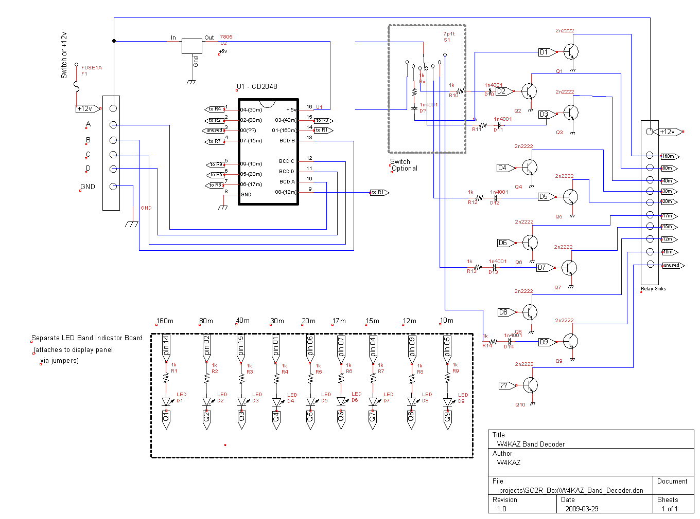
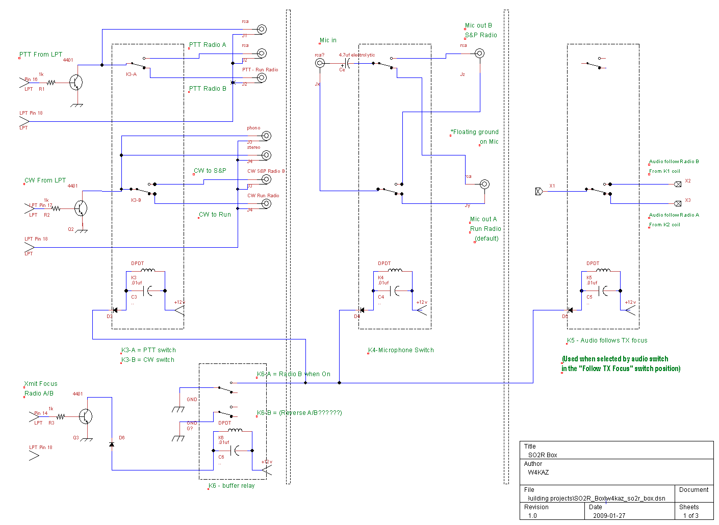
Chasing down the RFI caused by inserting all of the home-brewed SO2R components into the station set up was a useful hands-on experiment. Annoying, but certainly educational. I verged on ordering the ARRL RFI tome, but now the thing is fixed, owning the reference seems less urgent. Might be worth reading though…..probably quicker than re-inventing each technique personally. To start, the shack layout resulted in a few less than ideal situations. Both radios are side-by-side, separated by about 300mm. The computer that logs and controls both radios is on a rolling cart normally kept close to the station desk. The computer was also being introduced into the audio chain as the DVK, and I was also working towards routing the mic audio through the sound card full time. The cramped space on the desk is further reduced by the antenna switching controls and an antenna tuner. One set of bandpass filters is built into a relatively large computer case, and that occupies much of the top shelf. No RF problems were noticed on CW, but on SSB the audio was terrible, and I got many reports to that effect. Apologies to those who were exposed to it. The unshielded plastic enclosures used may have contributed to the problem, but so far most of the trouble has been corrected by applying the normal RFI kludge, clamp on ferrites. Shielded enclosures probably can’t make the problem any WORSE though. The audio stream for the Yaesu FT-920 was relatively easy to clear up. Three or four turns of cable through one or two ferrites seemed to do the trick. The K2 was more difficult to tame, but it was also the furthest from the computer. I expect that the longer audio cables needed to reach the K2 made better antennas for picking up the stray RF. The cables used are a mix of CAT-5 and shielded RCA audio cables. The CAT-5 cables carried the mic audio, PTT and CW from the So2R box to either radio. In addition to the ferrites, I also routed the audio from the computer through an isolation transformer. That step alone almost completely solved issues with the FT-920. Using a separate power supply for the SO2R box resulted in acceptable audio - better, but not BEST. Two of the issues were a big surprise – and I only discovered them as RFI ingress points because I reached the point where I was determined to cover every base. The separate power supply was an issue that was unexpected, but should not have been. NT4D has made that point to me several times over the years. Unfortunately good advice often falls on deaf ears. I have heard the gospel now…. The one that I really dd not expect was that the PTT line might be an RFI source. It became obvious this was a source when I methodically disconnected various cables on the K2 end of the chain. Low and behold, once the PTT line was disconnected from the SO2R box – no more RFI. I may now re-visit the entire chain, substituting a better quality cable to see if there is any difference or if fewer ferrites might be required. It took three ferrites with about five turns on each to subdue the RFI ingress from the PTT line. Here’s a summary of the mitigation steps taken to end the RFI issues.Problem #1: Problem #2: Problem #3: Problem #4: Problem #5: Add isolation transformer in line with audio from the computer before going into the SO2R box. Putting the transformer at the input to the SO2R box was an arbitrary choice – I don’t know if its location in the audio stream is of great consequence in mitigating the RFI. Its placement there ensured only one transformer was required, since all audio is routed through that location, not being split until later in the SO2R box. The location was convenient – perhaps not ideal. Caveat: It is possible I also did something else inadvertently which helped solve the problem, but after a couple of weeks of head scratching and trial and error, I can say that UNdoing any one of #1 thru #5 will re-introduce some amount of RFI. The problem with the PTT line really has me perplexed, but I guess it is in close proximity to the audio cable at the radio mike jack, so any RF on the PTT line is probably getting into the audio there. After all of the trial and error, my impulse in the future will be to add ferrites on all control cables on both ends, and immediately after they enter/exit each device. A recent conversation with N1LN caused me to dig out the schematic for my slightly customized K9AY, built back in pre-blog 2006. In general it has been a great antenna, and it has earned its permanent place in the antenna farm. In its current location, it is not as good as it was in its original ‘test of concept’ location. Practicality won out over performance. The antenna now occupies a space in the rear corner of the yard. That permanent location places it in close proximity to a chain link fence on two sides, and a storage shed is nestled into its NW quadrant. Significantly less than ideal location. This location reduces the effectiveness of the F/B ratio, but the lower noise level makes the antenna a better choice for RX on both 160 and 80 in most cases. When conditions on 160 and 80 are QRN free, the transmit antennas are sometimes better on RX. Sometimes. On the days where noise is an issue, the K9AY is almost always a better choice, especially if there is also QRM which can be nulled off the rear of the K9AY. I built the antenna as described by K9AY, with the additional mod to provide control voltages on a cable separate from the coax. I was also forced to use the SPDT relays I had on hand at the time of construction. The transformer used was constructed on an FT-125-K core, with 8 turns on the low [coax] side and 27 turns on the high[antenna] side. The antenna ground floats, i.e., it is NOT tied directly to the coax ground at the feedpoint. The KazShack customized schematic that resulted from the mods….PDF format only. The external relay controls were built into a small ‘Lock and Lock’ food container. The lock-n-lock box has proven to be a great choice for an el-cheapo waterproof enclosure. The gasketed lid locks firmly onto the box – not a single leak after five years. The control cables and terminals were placed on the ground facing side, and the box was mounted on a small piece of scrap aluminum angle that happened to be handy at the time of construction. The whole thing was given a random brown and green overcoat of paint for a bit of camo and UV protection. So far so good, and the plastic appears to have remained supple in its partly sunny location. Several radials were added at the base, attached to the antenna ground only. The chain link fence reduces the F/B ratio, but in certain instances the level of offending QRM/QRN can still sometimes be dropped by several S units. It performed much better in the free and clear test location, but that was just not practical. Less often discussed in ham circles, the K9AY is an OUTSTANDING AM broadcast band SWL antenna. I have been able to catch every nighttime LSU game as broadcast by WWL 870 in New Orleans. That is not always possible on any of the transmit antennas. The antenna doesn’t compare to a 2 wave length beverage, but it sure beats the crap out of listening on the transmit antennas in high noise conditions. A pennant, flag, or EWE might be slightly better, but all are less practical given the space available. Overall, I’m very happy with the performance of the K9AY rx antenna. Engineer the possible. This home brew SO2R controller project follows the “old-n-busted” theory, and is based on the design by N6BV in the ARRL Handbook, as well as some input from K4QPL. In summary, it is built around the use of an LPT port for computer control of the CW, PTT, Radio A/B, and band data. As previously outlined, the LPT port is less expensive and easier to accommodate – even if obsolete. Hence “old-n-busted”. I expect to be able to bridge the gap to USB at some point by adding a K1EL WinKeyer, and the Piexx SO2Rxlat dongle. The rig control is still accomplished via a serial port for each radio. The LPT parallel port is used for PTT, CW, transmit focus, and band data for one radio. The K2 band data is a separate option not installed in my K2[another void the Piexx SO2Rxlat dongle will solve]. As it stands now the only parts missing for a conversion to USB device control are the WinKeyer and SO2Rxlat devices. Everything else in the SO2R control chain is home brew. There are several resources available that block diagram the components needed inside the shack for SO2R[e.g.,see DL1IAO, for the W5XD SO2r Box].  For ease of use and construction, the heart of the SO2R box breaks down into four logical units which were built into three separate boxes. Band Decoder: One of the peripheral boxes will provide automated band switching driven by the logging program[or directly from a radio] by acting as the band decoder. Most logging programs provide band data in the “BCD” format, and Yaesu radios provide that format via their hardware dedicated band data outputs. The binary coded band data make the design of the decoder relatively simple. In hindsight, it seems like a good idea to expand this component’s abilities by using a set of relays to provide for either positive or sinking switching. This is a consideration for driving band pass switches or antenna switches, and is also a design factor for home brewing those components.  The internal view of the band decoder Band decoder schematic. PNG Image, PDF file For those looking for an inexpensive band decoder solution, the Unified Microsystems band decoder looks like a real bargain and could easily be incorporated into a home brew design. To build a band decoder, it is probably better to start off with the Unified Micro unit and build the support hardware around it. Audio Switch: The second is a simple peripheral to the main SO2R box is a simple remote switch. This device itself is simple, yet it really makes the SO2R a lot easier. This device was subdivided into two physical component parts. The actual relay board that switches the audio was built on its own small pc board and mounted within the SO2R box. The user controls are mounted in a small project box. The small box sits just above the keyboard on the desktop. For my own preferences, it seemed better to have one small “remote” user control box for switching in the heat of battle. The remote has a rotary switch to control the headphone audio, and it can choose either radio individually, stereo with one in each ear, stereo with left and right reversed, or it can be set to have the audio follow the transmit focus. It also has a momentary contact switch for each channel, which can be used in stereo mode to listen to either channel for as long as the switch is depressed. The remote switch control is connected via a Cat-5 cable to the SO2R control box. The control box and its rats nest of wiring can be placed away from the station controls. Remote: The momentary contact switch feature will soon be enhanced to correct an original construction oversight. Parallel connections for the momentary contact switches will be added to allow using a footswitch. That will provide hands-free audio switching when in stereo mode. That is important, as I need the hands free to type and deal with CW and radio tuning. Hat tip to K4QPL for the idea. Remote locating allows both the main SO2R box and the band decoder to be located away from the other major components in the station. That highlights the single caveat I experienced – RFI on SSB. After experiencing RFI problems during ARRL SS SSB, both of these units still need some attention paid to choking RF on the interconnects. Re-locating them a bit further from the RF hot spots and coax connections should also help with the RFI. Judicious and liberal use of clamp on RFI chokes seems to abate the problem. For some reason, the K2 seemed more susceptible to RFI than the Yaesu FT-920. The RFI source there turned out to be on the PTT line. A combination of ferrites and a diode in the PTT line finally tamed that hotspot. Note: in the PTT line, the PTT hot is at the radio’s mike connector, and it really didn’t sink into the thick head right away.  W4KAZ SO2R control box SO2R box schematic PNG Image, PDF file Audio switching schematic PNG Image, PDF file SO2R Box: The guts of the system all reside in the main SO2R box. It has inputs for headphone audio from each radio, CW inputs, PTT inputs, and microphone audio inputs. There is also an LPT Db-25 input for connection to the computer. The set up is designed to receive control input from the computer LPT port to drive some of the switching and provide band data. The main box contains two separate components. Two small perf boards were used to simplify construction. One board contains switching for the headphone audio. The other board handles switching for the CW, PTT, focus control, and microphone audio. The audio is normally switched via the switch remote, but it can also be slaved to follow the logging program’s transmit focus and be controlled from the main SO2R board. Future Migration to USB: In order to migrate to a logging computer with USB ports, it should be a minor change to replace the LPT cable with a USB connection via the Piexx SO2Rxlat device. By making the components LPT port compliant, the SO2R capability can also remain backward compatible with an older computer that has no USB support, running Writelog. Just in case the only option is an ancient junker from someones junk bin. The SO2RXlat will also provide band data for both radios via a single LPT DB-25 connector. Postmortem: The total cost in parts was not large. The 4401 NPN transistors, relays, connectors, bypass caps and diodes were all generic ‘project part’ items I have been accumulating over the past several years. I have gravitated towards using RCA connectors because of the availability of inexpensive sheilded RCA cables and the low cost of the connectors. The CD2048 IC for the band decoder was a dedicated purchase, and were around $1.98 USD. The amount of time put into construction, the biggest real expense, amounted to about 15 total hours, spread over a long period in several hour long increments. I spent more time debugging the RFI issues. The RFI is probably partly due to using plastic enclosures, but these enclosures were easy to come by. In hindsight I would add ferrite beads on to all interconnects inside the boxes. The ferrites on the interconnect cables create a bit of additional clutter and impede quick wire pulls. Kludgy. The remote switch has since been modified to add a jack for an external switch to concentrate both channels on either the left or right radio. This will allow for use of a foot switch and will allow hands-free audio switching. Best of wishes to the team of operators soon to be operating as YI9PSE. The DX-pedition is of particular interest personally because my friend Jack, W0UCE will be one of the team members. Jack joined our own IOTA operation last year, and is fine CW operator. When he dons his “Chef Archie” hat, he can also deliver some of the tastiest meals you have ever had. The YI9PSE team has a good group of operators – this will be a fun one to try to work. Bolshevik Baghdad Bob Been Banished…… Funny how the Bolsheviks hate being parodied. Truly remarkable. Some of the e-mails are priceless examples of “liberal” “tolerance”. [Hint: neither word is actually appropriate.] For a less offensive example of Bolshevik discourse, here is a case in point:–>http://www.eham.net/links/rating/11229 But then political discourse, while more appropriate in a blog than on 75m nets, is not really appropriate in a ham radio blog. Now is it?  Bolshevik Bob will need to start his own blog elsewhere. All hints of Bolshevism will be banished from this small slice of the world at large.
 Best of Baghdad Bob The weekend over at the N1LN/N1YXU was a lot of fun, as always. Somewhat bleary eyed at the end, but that is to be expected. The results…..2629 QSO’s, 435 mults, score of 3,417,795. The propagation was not what we hoped for, and conditions were not close to what we enjoyed for ARRL DX CW only a couple of weeks ago. Not a shock, and probably the only disappointing aspect of the event for me. We laid plans to open up on 40m and 80m. In hindsight, that was probably not the best choice, but it sure made sense at the time. 40m was decent at the beginning, but 80m wasn’t there yet, and as the lead-off op on 80m I was too slow to react to the actual conditions. Live and Learn. The low bands were tough sledding all weekend. 40m was the money band in the first 24 hours, then 20m took over the lead role. It was extremely difficult to find and hold runs all weekend. 15m was fair on Saturday, not too good on Sunday. We worked JA’s on both 15m and 20m late Saturday afternoon, not many on Sunday. The conditions Sunday were maybe even a little worse than those we enjoyed for CQWW in October 2009. Some of the QSO’s were interesting. Beaming Europe in the local morning, just after 1200z, I worked an HS0. Not just once, but one each on both Saturday and Sunday mornings. That had to have been long path propagation, because the short path was at enough of an angle off the beam to be in a null. Both stations had easily workable signals, no QSB on either. The stations that did call be on 80m at the start of the contest were all solid copy, showing that the band was indeed open at the time. Just nobody S&P’ing down there early in the contest. 40m produced a solid string of QSO’s in the hours following the EU sunrise. Probably just indicative of a lot of casual ops having some fun after a good night’s rest. While going up and down the bands, I was hearing relatively few US stations calling. That made it more likely you could end up stacked on top of another station calling. Curious results ensue…. In his soapbox, N1LN describes some of the conditions from his own POV. I would need to agree about the QRM. 20m was a real zoo. I’m sure there were many stations calling that I could not hear through the heavy QRM. Many stations were stacked in layers calling CQ, and it was difficult to find a place in the bedlam. Stations would then park as little as 700hz up and start calling. A real zoo. I just gotta start working on increasing the CW skills. At least I can be prepared – just in case propagation never really recovers. The Good:
The Bad:
The Ugly:
The Audio(source unknown): Â
Band QSOs Mults ------------------- 160: 74 43 80: 193 71 40: 622 98 20: 1064 104 15: 589 100 10: 87 19 ------------------- Total: 2629 435 Total Score = 3,417,795 For a rainy day. 137 years of Popular Science free for browsing. Thanks PopSci and GooG. Leave it to the RedmondGeeks to create a useful tool but leave it undocumented rather than make it easily available. And a big thanks to NumberOneSon for showing me the trick. There’s a feature for Windows 7 users called GodMode, which is simply a tool/folder that has a lot of the more useful system administration tasks grouped together in one place. [As opposed to navigating five screens to get to them.] All that is required to use the feature is to create a folder then re-name it. See the link for the details or just goog up the word “godmode” for yourself. No use re-inventing the wheel here. [hey! I didn’t name it…] OBSOLETE: Versions after version 11 are much better.  Disregard if using a version of Writelog after 2011. [w4kaz, 20150101] ENVIRONMENT: The following applies to an install of Writelog on a Windows 7 64 bit platform with User Account Control enabled. Probably works for any Windows 7 version. It may also apply to Vista, but that version of Windows has not found its way into my hands, so experiment at your own speed. All installs were done under the administrators account, and testing of the application done in a limited user account. No special permissions were granted to the limited user, nor to any of the directories. BACKGROUND: The new BlogBox is not used down in the KazShack dungeon, but is the day-to-day computer. After a contest, I move the log file up to the main computer and use an install of WriteLog on that box to spew out the Cabrillo, and ADIF backup, and the reports. For my own nefarious reasons, I chose to set the new BlogBox up with an administrative user, and do all of the day-to-day activities within a limited user account. WriteLog is still backwards compatible with older versions of windows, and runs well even on systems with limited resources. That is something that is a useful feature, as it allows a wide choice of hardware platforms to be pressed into service. Plus, I just damn well like WriteLog better than anything else. But since Writelog was designed before the day of user accounts there are some adjustments that need to be made to get it working in Windows 7. THE INSTALL: One approach used by many is to disable User Account Control[UAC] and run the system as the administrator. That’s a judgment call. Diametrically opposed to the goal here…but used with success by many. Another approach that seemed to work is to install it under an account with administrator privileges. But that also falls short of the goal, which is to get it going under a limited user account. When installed as the administrator, the user accounts were able to run the program, but not able to save the configuration settings. The approach that seemed to work is to install WriteLog into its own directory[I named it c:\writelog_install_home]. The install went without a hitch. The real trick is simply to find where everything is right after the install. The important part is locating the “writelog.ini” configuration file. For whatever reason the RedmondGeeks in Windows 7 [and maybe Vista] have an environment variable [“appdata”] that is used for hiding certain bits of data under UAC. The term “hiding” is used deliberately since the directory referenced by the environment variable is indeed hidden. Finding STUFF:
The basic install is all pretty easy once you locate the files. The critical file is the configuration file, “writelog.ini”. In this sort of install there are actually two copies of writelog.ini. One copy is in C:\windows. That copy is an abbreviated version, which has what I expect are the bare minimum bits of info required by WriteLog to run. [NOTE:After installing the program several times it is possible this copy in C:\windows could just be cruft left in place from a previous install.] It seems likely that “writelog.ini” is used to initialize the program. Probably best to ignore that copy of Writelog.ini, and leave it undisturbed. You will need to have admin privileges to edit it. The second copy is stored under the c:\users\xxxxxx\appdata directory in the sub directory \VirtualStore\Windows. The full path in my install was “c:\users\w4kaz\appdata\VirtualStore\Windows\writelog.ini”. THIS is the file used to store config settings for the logged on user, and it is here that customizations should be added. The user copy is created for each user individually and uniquely. That copy is the version that can be customized as required for the particular situation. A lot of WriteLog users have custom versions of their config file for different situations. Rather than maintain numerous copies of the file, it might also be appropriate to define a separate user for each situation. Then all of the copying/management of config files could be avoided by simply logging on to the appropriate user. That’s enough to get the program functional as far as opening logs, exporting reports and files. Testing connectivity is to peripherals is more difficult, since the shack is not in the same location and there are no USB dongles yet in use in the KazShack. The defaulted directories were as follows, after the user had opened the program, and done a “save config”: [Install] [Configuration] [Multipliers] Wave files and data files are defaulted to the user’s documents folder. Customize those as needed. The only real curiosity is that the user writelog.ini install directory was not updated in the final install to reflect the actual install directory. Its probably best to update that entry to reflect the actual installation directory. Installed in this manner I have not yet run into anything that required administrator privileges, or that Writelog be “run as administrator”. But admittedly, I have not yet tested keying CW, .wav file audio, or rig control. The BlogBox is not the computer used for contest logging, nor do I use any USB dongles at this point. In the end, admin privileges may indeed be required for full featured usage that bangs away on the com ports, but in a limited use it is not required. Best guess is that LPT keying probably is more complicated, if possible at all, and that a Winkeyer would probably work easily via USB. CAVEAT: After I was satisfied the main program was functional, I went through the Writelog directory and executed each of the utility programs. The “tuning indicator and audio snapshot” program received an error window trying to edit the system registry. That program is for use with RTTY, a mode I am not using, so it is not clear to me that the program has actually failed. After acknowledging the error, the program appears to load and be ready for action. UPGRADES: For these tests, Writelog v10.70c was used for the full install. Upgrades 10.71 through 10.75 were then applied via the administrator, with no problems encountered. The program ran for both the administrator and the limited user accounts. And dats da fax, jack….. |
||


