Radio W4KAZ Thanks for stopping by the virtual KazShack. Feel free to comment - I often approve them.
|
By w4kaz, created on 2008.10.06 at 06:53:15 | last changed on 2010.10.01 at 09:07:47 | The shack is still in disarray but there is light at the end of the tunnel. The acorns are raining down like hail, so the leaves are not far behind. It is time to wrap up the shack re-assembly before leaf raking(and contesting!) season arrives in earnest. I need to keep the leaves from carpeting the grass, or else the small amount of grass will be croaked by the carpet of leaves.
The long outstanding antenna switch has been finished. I already had most of the parts ready. The remote switch and inside switch box have been assembled for quite a while. I finished the outside enclosure over the summer. During the last couple of weeks I put connectors on the control cables and ran them from the shack to the location chosen for the switch. One of the first really pretty fall days dropped in on Saturday so final assembly of all of the components got DONE! Sweeeet.
That same beautiful Saturday was perfect for performing maintenance on most of the antennas and their support ropes. Time to adjust the 20m and 40m dipoles. They were both too short, and resonant above the SSB segments. Both are now resonant just above the middle of the CW segments on their bands.
The 15m/10m antenna is a nested rectangular loop. It is the same size or length of wire as a normal quad loop, but instead of square, the vertical sides are just a bit less than 2 times the length of the horizontal sides. It is fed at the bottom(a short side, and closer to the ground) and is thus horizontally polarized. My own antenna differs somewhat from this website description and the original idea goes back at least to K6STI. In my own version, I use a length of aluminum channel as the top horizontal. I’m really happy with this antenna. When the bands open, it works well. Its most endearing characteristic is that it is easily rotatable, as it hangs from a single support. It has tag lines, which are used to rotate and secure the direction.
The rectangle also has the benefits of any quad loop while showing a nice 50 ohm match. Sweet. I had been feeding each loop from a single feedline. Since I’m planning ahead for the use of the band pass filters, it was time to put each on a separate line. Since the antenna needed to be dropped anyway, I also put up a set of fresh ropes.
Each loop required re-pruning after they were separated. Both required about four inches of wire added to bring their resonances down to the CW band segments. They also now show more a broad coverage at less than 2:1 SWR. Using a single feed line is a bit of a trade-off. You trade a bit of bandwidth for the convenience of a single line.
Since they are now using separate feedlines, I could have gone to normal equilateral quad loops, and maybe used a balun or quarter wave matching section. It would have raised the average height above ground. This was a bad idea for my situation given their location, because the increased length of the horizontals would make them more of a snaggle problem with adjacent trees.
I’ve also got the K2 160m module installed, so I’m looking forward to that. Band Pass Filter Fever is on hold until I can scrounge up enough parts.
In a very unusual turn of events, Murphy was off bothering someone else Saturday. 🙂
By w4kaz, created on 2008.09.21 at 05:39:16 | last changed on 2009.07.06 at 10:22:04 | So, lots of interesting material to read through listed in BPFF Part 1, and much of it is available via the internet. Catch the whole series of w4kaz band pass filter musings.
This project is not really new for me but just something that was recently underscored by recent operations. Deciding which projects to tackle became a matter of choosing those that I thought are ‘possible’. For these purposes ‘possible’ is defined as
- the parts or substitutes are readily available
- the construction appears simple enough for clumsy fingers
- the final tuning is simple
These criteria knocked out the W3NQN filter and the N1AL because I thought tuning the multi-filar toroidal inductors would be enough to exceed my level of patience. The W3NQN design is well recommended functionally, I just thought the tuning procedures were going to prove too difficult. As a side note, the Toroid King sells a kit of the required toroids for the W3NQN filter, and the DL2BNU article describes a method of tuning that is simpler than using a VNA (that I don’t have). The N1AL design bothers me because of the taps on the multi turn inductor and the trial and error tuning. The ARRL sidebar on the N1AL project is interesting, stating that the filters interact to give nulls on the even harmonics. Curious.
A couple of years back, I built the K4VX filters. That project is relatively simple. Tuning can be done with an MFJ antenna analyzer or using a grid dip method. My own analyzer seemed sufficient, and I was able to build filters for 80m, 40m, and 20m fairly simply. The 160m was more difficult to tune and I never achieved a good SWR. It is now being used on the receive antenna to filter out nearby broadcast QRM from 680 and 850 on the AM dial.
The first real problem I ran across came when the 20m filter was mistakenly put into a high SWR load. FUBAR! The damage manifests itself as a high SWR into the dummy load, and the resonances have changed. I suspect the toroids were damaged by overheating. The capacitors used were silver mica’s, and their values seem unchanged.
Another filter project recently bubbled up through the dogpile stream of data. I ran across the NVARC “Ugly” filter project. Besides having a good write up, their project is billed as a “no tune” design.
So far, that seems to be mostly correct. I’ve had success with the two assembled so far. The 20m filter came in with a resonance a bit low, but the loss through it is in the area of about .5db. No tuning required. The 15m filter is actually centered right at 21Mc, and the SWR is dead flat at 1:1 across the entire 15m band. It’s showing insertion losses of about .7db. I have not yet given either of them any on-air trials, so that’s coming later, but the transmit smoke tests into the dummy load(three one minute intervals, 15 seconds apart) showed very little heating in any of the components. After cutting power, the hottest components were just barely warm to the touch. Sweet.
Not so sweet with the first attempt on the 10m version. It originally showed a resonance around 27.500 with an SWR above 2:1 at the lowest. The NVARC document had a discrepancy, which has since been corrected. Re-building the filter as specified in the updated instructions corrected the resonance. It is now good over most of 10 meters – the SWR minimum is around 28.500, and is about 1.4:1 at the bottom of the CW segment, but the insertion loss is low, only about .5db. A look at their VNA sweep shows that it is resonant at the high end of 10m and above. My rendition shows a double dip minimum in the SWR, one centered on 28.500 and a second broader dip at 31.500. Their VNA sweep of the SWR on their filter is very similar to my own SWR plot taken with an MFJ-259, so I declared my reproduction a success.
The NVARC filters are made with air wound coils, using common schedule 40 PVC pipe sections as the coil forms. The guidelines for winding the coils are fairly accurate, and I didn’t really have any problems winding nice, tight coils. The winding process IS a bit hard on the hands, but not impossible. It might be difficult for someone suffering from arthritis. Post winding testing of a set of the coils with K4CZ’s LCR meter showed the inductances on each to be quite close to the value specified on the Ugly Filter schematic.
It occurred to me that the NVARC filter designs might be built just as easily using toroidal cores. It should be simple enough to use an air wound set to come up with resonance values for each section. That will allow for easy rough tuning, similar to the K4VX method. I guess they could then be fine tuned for maximum smoke with an RF probe and a multi-meter. If the air wound design seems to have good performance, I may try one out with toroids. But credit must be given W1XP and the NVARC crew – these filters are easy enough to re-produce, and none of the three required any sort of tuning.
Ultimately I would like to have a pair of each type NVARC and K4VX on 40m and 20m to test forsuitability. For the time being, its a project on hold to gather resources. I gotta get on the 160 mod for the K2, not to mention re-painting thefasciathe roofers had to fix last month when installing the new roof on the QTH.
Note: There will be a bit of a time gap in this “BPFF” series. I have several other projects going on, and of the radio related items I really need to get on the K2 160m option.
First in series: Band Pass Filter Fever – The Tangled Web – Part 1
Next in series: Band Pass Filter Fever – The Guinea Pigs – Part 3.
By w4kaz, created on 2008.09.13 at 05:39:27 | last changed on 2012.03.26 at 10:36:24 | Amended 3/25/2012: Again – re-Fixed broken links, added new links for VK4EMM and KG4JJH reference material
———————————— Begin original Post ————————————-
On occasion I’ve noticed I have a tendency to get wrapped up in an idea I can’t shake. Obsessed might be a close description despite the negative connotations. It’s not quite an obsessive mania, nor is it complete fixation. Perhaps fascination is closer to the truth. A “passionate fascination” sure sounds better than “obsession”. Not much difference semantically, but there it is.
Oddly enough, the most recent subject of interest is band pass filters for HF. (Reeks of geek, no?) Conjured by both this year’s(2008) Field Day and the IOTA operations, it is something I became interested in out of need. Commercial filters are available. It also seems that it is still possible to home brew decent band pass filters for relatively low costs. There are several designs widely available. Using coaxial stubs is also an option.
Homebrew is more fun, and in this case, possibly even less expensive. The difficult part of the problem for me is a simple method for tuning the filters. I don’t have access to a lot of test equipment. Also, some of the designs are easier to build than others. Selecting appropriate parts is also a bit of a problem in some cases.
Ideally, a good band pass filter will have a low insertion loss over the pass band, and a high level of rejection outside the pass band. I’m no Werner Von Einsteeen electronics whiz, but there are going to clearly be some trade-offs there somewhere. So knowing your application can guide you to deciding which trade-offs are appropriate.
A look at commercial filters is also helpful. It i$ certainly ea$ier to buy off the $helf filter$. Filters are available from Dunestar, I.C.E., and the W3NQN filters from Array Solutions. I’ve also run across a set of high power filters, but can’t find the link. EU I think. 4O3A also has a version of high power filters.
In an article by Peter Pfann, DL2BNU (German language only)of the Bavarian Contest Club, there is a chart of test results as conducted by DL2BNU. Peter’s chart, page 3, shows the measured insertion loss for most of the filters on each band, lacking only measurements for the I.C.E. filters on 80m or 160m. His chart highlights some of the trade-offs. The Dunestars have better attenuation outside the pass band, but at the cost of higher insertion losses. The I.C.E. filters are least expensive and have low insertion losses in the pass band, but generally show slightly less useful attenuation in the adjacent bands.
I expect to need two sets of filters. I’d like to have them for exploring SO2R as well as for use at Field Day and IOTA. All of that operating is at low power. So – a low pass band insertion loss is desirable.The other significant considerations include total cost, availability of suitable components and materials, and ease of assembly. Finally – they need to add value by !FILTERING! That’s the whole point, right?
Proceed to Part 2 -Band Pass Filter Fever – Untangling The Web, or follow some of these additional references below.
****
****
Primary web references:
The Nashoba Valley Amateur Radio Club, the NVARC “Ugly” filter project, by W1FP and KD1LE.
Article by Peter Pfann, DL2BNU of the Bavarian Contest Club, a construction project write up on building the W3NQN filters.
RF Filters, ARRL Technical Information service page with filter definitions and article references
Band-Pass Filters for HF Transceivers by Lou Gordon K4VX QST September 1988
W3LPL Receive Only Band Pass filters via K1TTT technical references site.
K2TR Coax Stub Filters via K1TTT technical references site.
K3NA Coaxial stubs via the K1TTT technical reference site
Clean Up Your Signal with Band-Pass Filters, By Ed Wetherhold, W3NQN 1998 ,[ARRL Members only] 2 parts [ –Part 1– , –Part 2– ].
Additional references:
Excellent advice from KG4JJH about building and tuning W3NQN filters. (added 2012/03/03)
Band Pass Filters for Contesting by Brian Bartlett, VK4UM and John Loftus, VK4EMM
QST Product Review of Dunestar commercial filters Dunestar Model 600 Multiband Bandpass Filter, QST March 1995
Dunestar bandpass filters
Array Solutions commercial filters based on W3NQN QST article June 1998
Industrial Communication Engineers LTD, ICE commercial bandpass
filters
Inexpensive Interference Filters by Alan Bloom N1AL, QST June 1994 (ARRL members only)
Narrow Bandpass Filter [ARRL Members only] article in QEX by William E Sabin W0IYH
Band Reject Filters by AF4Z
amended, 9/15/2008(tnx K9ZW!) :
“Managing Interstation Interference – Coaxial Stubs and Filters” by George Cutsogeorge, W2VJN, available in hardcopy from International Radio for only $15 USD.
amended, 3/31/2010:
K9YC, Some Q&A About Coax and Stubs for your HF Station. Good stuff.
Amended 9/30/2010: Fixed links broken by ARRL website re-design
Circular Link-amended, 7/06/2009:
This excursion into filters turned into a series of musings, so there is more on the process andmethods of discovery as I re-invented the wheel. It is a circular link because it also takes you back here. Oh No!
–
By w4kaz, created on 2008.07.11 at 07:40:29 | last changed on 2008.07.11 at 20:26:15 | K8ND has acollection of SO2R shack photosthat should help with getting layout ideas. Some are simple and some are elaborate. Some layouts appeal to me for different reasons.
I like N4TZ’s layout because the Vee shape allows some access to the rear of the gear. My shack space was too limited for this, so my own design is on wheels – I can pull the whole kit away from the wall for snaking wires.
I also like the K3PP shackbecause I like the simplicity and versatility of the small shelves for vertical gear stacking. My own cabinet is somewhat less versatile, but good enough for now.
By w4kaz, created on 2008.07.09 at 06:32:13 | last changed on 2008.08.03 at 11:30:43 | I spent some time re-arranging the station area in the basement cubby-hole after unloading the jed-clampett-mobile(my stuffed to the gills truck) in the days following Field Day. Here’s a picture to remember it by, because I’m sure it will soon again be covered by several years of miscellaneous unrelated items. Things seem to find their way their over time.
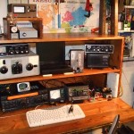 Here’s what the operating position is looking like after I re-sorted everything out after field day of 2008. On the bottom row, the FT-920, Diawa wattmeter, and Elecraft k2/100 w/KAT100. On the next level up, an MFJ tuner on top of MOAT, the “Mother of all Tuners”. centered is the junker laptop and K9AY switch, then the Yaesu SP-8 speaker with another MFJ tuner on top. On the top of the cabinet is the “wishful thinking”, a Ham-II control box(attached to nothing) and the switch box for an incomplete home brew remote switch project. Here’s what the operating position is looking like after I re-sorted everything out after field day of 2008. On the bottom row, the FT-920, Diawa wattmeter, and Elecraft k2/100 w/KAT100. On the next level up, an MFJ tuner on top of MOAT, the “Mother of all Tuners”. centered is the junker laptop and K9AY switch, then the Yaesu SP-8 speaker with another MFJ tuner on top. On the top of the cabinet is the “wishful thinking”, a Ham-II control box(attached to nothing) and the switch box for an incomplete home brew remote switch project.
The desk itself is something I designed and built five years ago. Its major shortcoming is the lack of space for a monitor. I was previously using a side cart for the computer and monitor. Since I now have an old laptop for my logging, I have it included in the desk set up. The side cart is now gone, but I will build one to match the desk at some point. The Ham-II controller is a place saver, since I don’t have any tower or rotatable antennas up….yet.
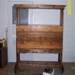
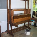 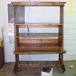 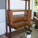
Top: desk with fold down door closed. bottom left: side view with one panel of desk surface opened. bottom center: front view with desk top opened. bottom right: side view opened
The desk itself worked out very well otherwise, since my operating area is so physically limited. It’s nice to be able to fold up the desktop. Since the desktop also acts as a fold-up door, I can close and lock it up if bneeded. The whole kit is on heavy duty casters, so I can roll the entire station around fairly without needing to be too careful. It DOES help to unplug everything before trying to roll off with it. 😉
In use, the desk level shelf and the shelf above are in easy arm’s reach. Anything on the top of the box is a stretch, so its somewhat inconvenient to put tuners and antenna switches up there. The very topmost shelf is mostly out of reach for me, so use it for storage. The area below desk level is perfect for the APC line conditioner, power supplies, and the fire extinguisher. The desk top is itself held by permanently attached steel cables, and two fold out brackets below the desktop. I wasn’t up to the challenge of pocketed brackets, so they are hinged to the front of the frame. The desktop is at 27 inches, which I find the best height for me, and it has a slight slope downward when open. Just enough slope that pencils will roll off. Grrrr. I did that on purpose. Sometimes I think it was a mistake, but it makes long periods of operating and logging comfortable.
The photos don’t show it very well, but the desk is stained in two different tones. It was a carpentry experiment that worked. If I can find the plans I drew up for it, I’ll post them. The construction is simple, using common dimensions of lumber available from any big box here in the US. The frame is constructed of 2×4 and 1×4 material.
The case is actually aseparatepiece, just sitting in the frame. It’s weight is enough to hold it in, as long as no one is goofy enough to try and sit on the desktop when its open. It is constructed of 1×6 and 1×4 lumber, some of which is edge joined to make wider pieces. All of the lumber is pine, so it tends to scar easily. I’ve been touching up the dents and dings with matching stain, and I like the lived in look the markings add to the piece.
With the desktop closed the whole thing is just over two feet deep, so it occupies a relatively small footprint. It is a bit less versatile than a larger flat desktop, but I needed a space saving solution. If I ever get the chance to move to a larger area, I’ll have a new project – matching extension pieces.
By w4kaz, created on 2008.05.31 at 20:23:02 | last changed on 2008.06.02 at 10:02:09 | I almost forgot to mention one of the more interesting “goodies” I picked up at this year’s Hamvention.
If anyone has fond memories of the Heathkit 5010 uMatic keyer, here’s the ticket. Its the CW Touch Keyer. The touch keyer is a set of capacitive paddles mated to a keyer.
I came very close to missing this entirely. Their booth was in plain sight on the floor of the arena, but I didn’t spend much time there. On a last minute walk through, we noticed their display, and began playing with the samples. Hooked! Sold! Cha-CHING!
They also sell the capacitive paddles board as aseparateitem, and that is the option I chose. I plunked down the cash for the P3 kit, because I’m not sure yet how I’d like the paddles configured. I’ve never liked using paddles. Iambic paddlesaggravatethe arthritic/carpal tunnel in my hand, even more than a straight key. My paddle “fist” really sucks. I don’t know that this will help any, but for only $20 USD, it is sure worth trying. Heck, it was worth the twenty just for the novelty factor – many folks won’t remember the heathkit keyer. I didn’t at first, but after a memory jog by NT4D, I remember seeing a set of these back in the days of my yoot’. I’d never actually used a set, but remembered seeing them.
The P3 kit went together in a few minutes of solder smoke. After initial testing, I now need to decide how to construct the contacts/paddles, and decide what sort of enclosure to use. The board itself is small and will fit into an altoids tin, leaving the tin mostly empty. There is also a P3SMD version, if you want an inexpensive gizmo for practicing surface mount soldering.
The light touch required on the display models is encouraging. The “complete” wired paddles have gold plated paddles, so I would expect pretty good life from them. They sure were fun to play with. But it leaves open the question of how to construct my own set. Thepossibilitiesare varied and numerous.
Inspiration will come. It always does.
By w4kaz, created on 2008.05.17 at 06:27:02 | last changed on 2008.05.17 at 06:52:28 | I see that Inrad has released the FT-920 roofing filter mod as ready to ship. I didn’t find their booth in Dayton yesterday, hopefully I will today(actually must have walked right past!). The mod is listed as $200 on their price list.
I don’t know that I can get one very soon, but my reason for keeping the 920 was to compare it to the Elecraft K2 under contest conditions. It would be interesting to do the testing as A/B/C to get a general idea of just how discernible any improvements might be, before roofing filter/after roofing filter.
I suspect the roofing filter may narrow the performance gap quite a bit, maybe even enough that it becomes a choice of which radio to keep. I’ll be especially curious how much it helps on SSB. There are enough loud stations within a couple of miles of me that it should be easy to arrange a test.
By w4kaz, created on 2008.02.26 at 10:56:04 | last changed on 2008.02.26 at 10:56:51 | After discovering that the Samlex was so ‘very similar’ to other well known brands, I bought one to replace my dead switching supply.
I’ll need to make some updates to my FP-1023 page. The new Samlex has some changes in the output filtering section. The new supply has a toroidal inductor for L2(instead of the rod) and different, larger value capacitors for the RF bypass at the outputs.
An initial comparison and search for birdies turned up very little, and nothing of concern, compared to the loaner Astron RS-35. The switcher had a few more birdies on 15m and 10m, but actually had NO birdies on 40m, while the Astron had three or four(one significant). Most of the other birdies were consistently present with either supply.
I plan to put the supply under load(i.e., the second radio transmitting into a dummy load), and hunt for birdies under load. After that, I’ll update the page, including photos of the new parts layout.
By w4kaz, created on 2008.01.18 at 13:48:09 | last changed on 2008.01.18 at 15:15:01 | After a bit of internet digging, and a few helpful e-mails, I turned up references to the website of N0SS. Tom’s web site is a trove of good advice on a variety of things. One of those things is the Samlex 1223 switching power supply. It just so happens that the Yaesu FP-1023 is a re-branded Samlex(i.e., made for Yaesu by Samlex).
I have put together a separate page to document some of this power supply information. That page will be updated as new info rolls in. Enough said here for now.
By w4kaz, created on 2007.12.23 at 06:52:17 | last changed on 2008.08.03 at 11:30:03 | Here are a couple of snaps of my LogiKey CMOS4 kit from Idiom Press. It was a joy to build and it is a FB keyer. It was one of the easier to assemble kits I’ve fooled with, and the supplied instructions are detailed and complete.
This keyer is also available fully assembled. In my opinion, soldering the kit requires a fine tipped soldering pencil. My smallest soldering iron was almost too big, but with a magnifier and bright lighting at hand, I muddled through.
Continue reading The Logikey
|
|


