Radio W4KAZ Thanks for stopping by the virtual KazShack. Feel free to comment - I often approve them.
|
By w4kaz, created on 2012.08.24 at 17:07:02 | last changed on 2012.08.29 at 12:38:38 | My testing sandbox server is running on an ancient Dell Optiplex 280 minitower, which has a P4 processor and 2gb of ram. Â Its been chugging along placidly on Ubuntu 10.04LTS. Â The 12.04LTS version has been popping up for a bit, and it seemed like it was being reported as a very solid release.
The install running in my VirtualBox partition went smoothly enough, but that was only a leap from 11.x to 12.04. Â Upgrading from 10.04 is a couple of levels to jump, so the possibility for problems increases.
So with some amount of trepidation I decided to run the upgrade process on the 10.04 sandbox. If the upgrade should barf completely, its not a tremendous loss.  If it works, the 12.04LTS version is supposed to be good through 2017(if I recall the upgrade notes correctly).
The upgrade seems to have been completely successful, with zero impact on the test bed. Â Sweeeeeet….. The 10.04LTS was mostly a plain vanilla install, but its nice that it made the leap with so little intervention.
This upgrade went far more easily than a prior upgrade(from 8.10 to 9.04). Â Very happy to see the Ubuntu developers have made the upgrade process so user friendly.
Very. Â Nice. Â Work.
So now the file server is good to go and can remain stable for the foreseeable future. Â Time to get back to hacking up some web apps for graphing the Reverse Beacon network data extracts.
Not so happy with the UNITY desktop, but at least it is easy to revert back to Gnome. Â Unity is kinda like the new Windows 8 – ButtHole Ugly. Â The very last thing I want is an interface that looks like a tablet. Â Bleh.
Never have understood why OS developers seem to think that 30 years of accumulated OS familiarity is so readily cast aside for their own vision of ease-of-use. Â Too little customer contact…. Â Most customers want their interfaces to function the same way they functioned yesterday(providing they actually worked yesterday), and changed only if they were broken. Â AKA, “New Coke Syndrome”.
Coke Classic pleeze…..add gold rum and lime….
By w4kaz, created on 2012.08.08 at 10:44:33 | last changed on 2012.08.08 at 10:44:33 | Added a new page to the skimmer station fun facts list.
The new page describes observations from using several different sound cards for both music and as the interface for SoftRock software defined radios and the CW Skimmer software.
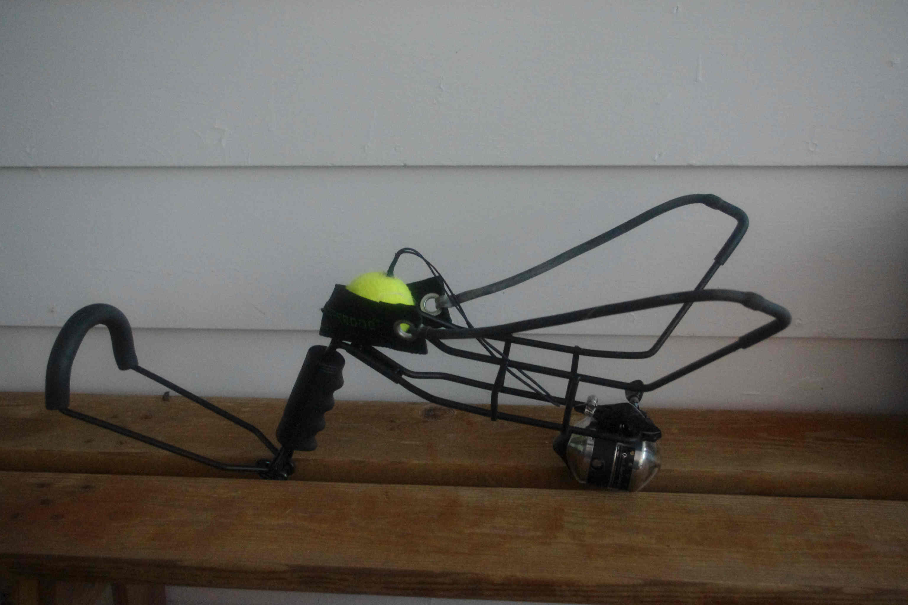
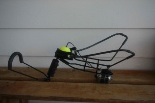
By w4kaz, created on 2012.07.21 at 18:26:11 | last changed on 2018.06.01 at 15:25:31 | Ran across the hyper dog ball launcher a couple of years ago, and the potential for re-purposed applications as an antenna launcher for hanging antenna supports seemed obvious.  It is not as much fun as a pneumatic launcher, but it sure is easily understood by any boy of 8.  No air pump required.
The modified hyper dogÂ
 |
 |
The normal slingshot type Wrist-Rocket/Crossman slingshot launcher has served the purpose for years, but not always without problems. Â A 1-oz(28g) lead weight works, but not without a relatively high rate of mis-fires, line tangles, and “Oh S**t!” moments. Â The hyper dog is a lot less likely to draw whining complaints from those inclined to wring their hands and moan about things that don’t really concern them..”See, its just a tennis ball. Â Now p**s off!”
The hyper dog has a much larger pouch designed for use with tennis balls.  A slight bit of hacking to the hardware gives a nice re-purposed tool for lofting lines into all of those beautiful deciduous biological antenna supports lining the back yard.  So far it has been a lot more reliable in actual usage than the ole trusty Crossman, although Field Day proved its not impossible to Dork Up.  [You Know Who You Are….lol]
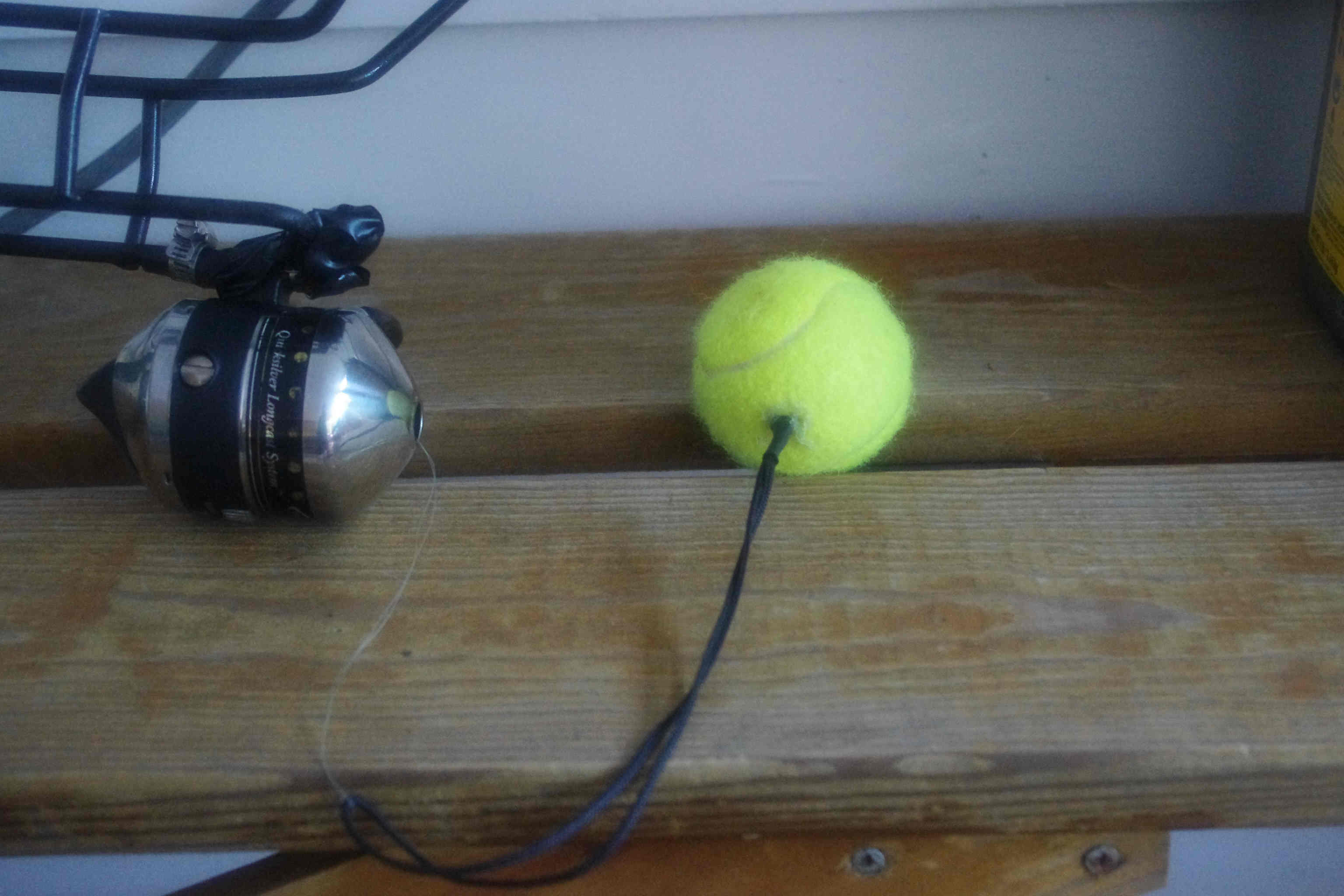
The reel deal:
Here the body was altered by adding a cheap spin-cast zebco reel picked up for $2 at a yard sale. A spinning reel or open faced casting reel might be better, but I have used the zebco’s since I was 6yo.  Being more familiar with the Zebco quirks and limitations is useful. For most, a spinning reel is probably the best option.  10 or 12lb test line has proven the best choice over the years – light enough to fly, strong enough to pull, and not impossible to break if it becomes hopelessly snarled at altitude.
The reel is simply attached below the ball carrier with a couple of hose clamps. Â That was later wrapped with an ugly mess of electrical tape just to reduce the number of exposed sharp edges.
Yes, the tennis balls work FB.
To modify the tennis balls, they were  just drilled with a 9/64 bit. A loop of 1/8th braided nylon cord is secured to a small hardware store drywall toggle bolt/spring bolt. Then just cram the bolt/cord through the hole, reaming the hole out slightly if needed[leaving most of the loop of cord hanging out!].   The base of the cord is sealed at the hole with a goop of liquid nails or hot glue or some-such.  The loop of cord is about 6 inches long(~150mm), and the spring bolt serves the same purpose it normally does by providing a large area preventing pull-out.  After drying completely – good to go.
The tennis balls seem to be a good compromise between weight and a non-destructive & non-threatening projectile. [Just don’t try to pull them back up through the tree-too fast!].   The ‘trick’ to success with it seems to be making sure the cord on the tennis balls clear the end of the slingshot. It seems to work best when the corded end of the ball is facing  up(i.e., at the top of the pouch when pulled back for a shot).
What’s the catch?
The only genuine problem I have with it is that it has a “long draw”.  Being impishly short my arms are not long enough to get the maximum performance out of the rig. But despite that it works much better than the regular slingshot with fewer snags and mis-fires. It easily sends the tennis balls up to about 90 feet(~30m).  The canopy here prevents anything higher, so no real top-end found yet.
I suspect golf balls would be the ultimate high-flying projectile for rural locations. Too much window glass and nervous-Nelly neighbors around the home QTH for me to try golf balls here.  A day-break early morning experiment for the future…. 😉
There is somebody here on the east coast marketing these re-branded as antenna launchers, and asking $80. Â See Radiowavz Hyper Hanger, now $90USD….
Too easy to homebrew from the $22 Amazon original to peel out 80 samolies 90 GreenStamps, but it is there as an option. (!~yikes~!)
By w4kaz, created on 2012.07.12 at 09:59:24 | last changed on 2012.07.12 at 13:00:20 | Well, their answer sure sounds plausible to me. Not close to April 1st….
It is a question most will ponder at some point.
Why 50 Ohms?
Link from KI3O via PVRC mail list.
By w4kaz, created on 2012.07.06 at 15:43:43 | last changed on 2012.07.06 at 15:47:31 | Operated 2012 Field Day with N4YDU and N4GU. Seriously considered entirely ditching FD earlier in the year, but finally decided to swing back into the saddle. Using the Central Carolina Contesters call K4FQU, how could I not?
K4FQU – Class 1A, Ops: N4GU, N4YDU & W4KAZ…. 1499 QSO’s(942CW, 557SSB)
N4YDU bird-dogged an excellent site by getting permission for operating on the north end of the Franklinton High school campus. The school has a horseshoe shaped service road around its perimeter. The north side of campus has a nice line of pine trees parallel to the service road which runs due E/W for about 500 feet. All in a mostly rural very RF quiet location. A very good Field Day site, one of the better sites we have used.
We set up the station near a break in the tree line. Operating as 1A, we put up two antennas. The 80m dipole was set up as a vee, broadside to N/S. The other antenna was the four band open sleeve dipole, set up facing E/W. The apex of both antennas was up at about 70 to 80 feet.
The wx threatened rain on Saturday, but that never happened. The cloud cover helped moderate temperatures right up until almost 1800z, so the set up was not terribly uncomfortable. The humidity levels rose all through Saturday night. A change in the WX about dawn Sunday, and a drier breeze picked up early Sunday morning. The WX was very pleasant for the duration. Probably one of the most comfortable FD weekends in a long time outside of the trips to the mountains.
Radio conditions did not seem all that good, but the rates were consistently good anyway. At times the rates were surprisingly good. N4YDU had unusually good rates in the “wee hours” on Sunday morning from 2:00am thru 6:00am(local), and turned the graveyard shift into a nice fat 350+ qso count.
For my own part, the best rates I saw were the first hour of my late evening shift from 11:00pm to 2:00am(local), where there was very fun rates on 80m CW as ‘fresh meat’. Getting a SSB run going proved difficult, but I managed to find a decent 40m frequency close to 2:00am Sunday morning, and N4YDU hit the ground running for the graveyard leg. The rates kept him awake. 😉
N4GU Power and Light supplied emergency power in the form of a 1000w Honda generator. We located the generator on an asphalt drive about 125 feet away from the station, and could not hear the generator at all over the ambient background noise of the location(School AC units, birds tweeting, road noise, etc.) N4GU also supplied shelter in the form of a couple of EZ-Up canopies. My own concerns about blood-sucking insects or T-storms were not realized, so the lack of side-walls was never a problem.
Over all the event went off without a hitch. Murphy was probably off elsewhere knocking over towers and breaking yagi’s at other more tempting FD sites. All of the overnight lighting was supplied by battery operated LED lamps, over concerns we might overload the generator. Generator overload was never an issue, as a Kill-a-Watt in the AC supply line showed that the power draw never got over 500w. With the single run station going, the draw was around 300-350watts.  The generator ran for about 7 hours between fill-ups, and was very easy on the gas. A sweet package.
Propagation seemed to favor the North-South paths for most of the times I was at the controls. With the 40m-up antenna at 75 feet, it seemed to under perform my expectations on 40m and 20m. That may have been just propagation, which seemed very short on 20m. In the evening, it did a better job out to the west, but I found myself using the 80m dipole on the 40m band more than I expected. Both antennas were fed with 450 ohm ladder line into balanced tuners, allowing them to be loaded where needed.
Reviewing the Reverse Beacon Network spots was interesting.
We wound up besting our QSO totals from 2011 by a couple of hundred Q’s. 10m never opened, 6m was a flop, and 15m was mediocre. But 80m, 40m, and 20m produced enough activity that we were able to keep the logging computer busy and the operators awake. Operating 1A with N4GU and N4YDU was just about perfect – both great ops and great fun. Class 1A also insured we were almost always ‘fresh meat’ somewhere, which made the butt-in-chair time fun as well.
The only real goal I had this year was to have some fun.  Mission Accomplished.
After action reflections indicated if we were to revisit the location we might make a few minor tweaks to the general set-up by re-locating the antennas, but probably nothing too drastic. The E/W roadway invites flat-topping the dipoles rather than center supporting them as inv-vee’s.  A few other minor station set-up re-arrangements. None of those would be of large consequence in terms of extra effort, but might pay QSO and comfort dividends.
K4FQU, 1A NC - Quick snapshot of score:
band/mode Qs       Pts
80 cw   222      444
80 ph   181      181
40 cw   440      880
40 ph   164      164
20 cw   231      462
20 ph   141      141
21 cw   45       90
21 ph   63       63
50 cw   4        8
50 ph   8        8
-----------------------------
1499 Â Â Â Â 2441
Pwr mult 2
Raw score 4882
Bonus pts
100% Emergency power            100
Public Location                 100
W1AW Message                    100
Online submisson                50
Total bonus pts                 350
Total Score     4882 + 350 = 5232 pts
*
By w4kaz, created on 2012.07.06 at 10:42:06 | last changed on 2021.05.06 at 21:08:01 | Created a page of links and several related pages of information on the ongoing construction of the CW Skimmer station at W4KAZ.
Because of the nature of the blog package used for this website, it is easier to save this skimmer related info on ‘pages’ rather than as a “post” because it seems like a project that I’d like to have semi-permanently documented, and have the documentation easily found. Whooop…there it iz….Incomplete, but slowly growing, and probably to be frequently edited in the short term.
By w4kaz, created on 2012.06.01 at 06:39:54 | last changed on 2013.06.10 at 08:31:17 | Tribander Plus? Plus what? Friends with benefits maybe?
Back in 2002 or so, references to the “open sleeve dipole” sparked a curiosity in the topic. Very few web references were available back then(in the internet dark ages). The article that initially tweaked the curiosity was N6LF’s article “A Wideband 80-m Dipole”, which built upon an earlier article by K9AY from 1995. The open sleeve idea is also mentioned by Bill Orr, W6SAI. Current ARRL Antenna books have information on this topic in Chapter 10, but that was not available in 2002. Not much else, but there are a few engineering references going back at least as far as 1945. None of which were readily available a decade ago. Time marches…..
Recently Joel Hallas, W1ZR, ran a couple of articles on the subject in QST. This article on adding 6m to a tribander duplicated an idea I had myself, although I was more interested in the possibility of easily adding 17m to a tribander. W1ZR uses the term favored by K9AY, the “coupled-resonator”, from K9AY’s article “The Coupled-Resonator Principle: A Flexible Method for Multiband Antennas†in the ARRL Antenna Compendium #5. K9AY’s “coupled-resonator” terminology is more precise and accurate as a general description of the principle for amateur uses. Yet my own fuzzy gray matter remains wed to the term “open-sleeve”, which is really an example of the general principle in a narrow usage.
More references are available today: NQ6K with a well written treatment used as a sloper, and DK7ZB has a good page briefly explaining the concept. Plus a new ARRL Antenna book(Chapter 10.4-10.5) entry. This is the idea in general terms. Placing another wire in parallel and “close” to another dipole allows you to feed the antenna at two different resonant frequencies. The feedline is attached to the longer dipole only, the second(and/or third) wires are excited parasitically. By carefully spacing the two wires, it is possible to get a 50 ohm match for both resonances.
Pretty handy idea….but….
O’course, the trick is in the details. Getting the spacing correct can be tricky if you are intent on that 50 ohm match. EZNEC modeling is simple enough for this gray cat, and it is easy enough to fiddle the dimensions of the second dipole and its length to get that 50 ohm match. It turns out you can also add a third dipole too, but the spacing dimensions become a lot more critical. Much like a fan dipole.
Generally, it seems that the higher frequency dipole winds up being slightly shorter than it would if it were a single dipole, and that is more pronounced as additional resonators are added. Harmonic combinations also seem more sensitive to dimension changes affecting feed point impedance. [NOTE: ARRL antenna book, chapter 10.5 contradicts my note of “slightly shorter”, indicating the dipoles might need to be slightly LONGER due to the capacitive coupling. Hmmmmmmm. Mayhaps wire spacing….?]
Outside the box of conventional
But what if we do NOT concentrate on the 50ohm match? What if we wish to use a balanced line feeder and a tuner, like for, oh, maybe a multi-band wire antenna for FIELD DAY? Something with improved and predictable radiation patterns over a non-resonant doublet?
That seems to be a pretty good option. The dipoles are resonant, even if they show an impedance that is not 50 ohms. Resonance does not imply 50 ohms….that is just a happy convenient choice since radios are designed to have input impedances coincidental with the general impedance of a half-wave dipole fed in the center. But an end fed half wave is just as resonant even though the impedance is nowhere near 50ohms.
With resonance the radiation patterns are more predictable, and there are less likely to be odd lobes as might be the case with a generic doublet. In the past we have used several different options for loading up a doublet on multiple bands, with mixed results. So in April I decided to cobble an open sleeve antenna together and try it out for a few days.
Models? We don’ neeed no steeeenkeeeng models…
No, but in this case the model was interesting. Going for a decent compromise of performance versus convenience, a bit of EZNEC tinkering showed that a 40m/20m/10m combination of elements might produce decent radiation pattern results for four bands. Input impedance? Maybe not so ideal.
The plan modeled was using 18ga ladderline for the mid-section, and attach legs on the ends for the 40m resonator. Spacing the 10m wire at about 1.5 inches in the model produced a more stable impedance curve for 10m, so rather than just taping the 10m wire to the ladderline, small spacers are used. Radiation patterns for 40m and 20m resemble normal dipole patterns. The 15m pattern is normal for a 40m wire pressed into 15m service – a dipole pattern that is breaking into two lobes with a nulled lobe perpendicular to the dipole. The 10m pattern without the 10m element would show the same butterfly pattern. Adding the 10m element makes a huge difference on both the radiation pattern and the feedpoint impedance in this instance.
Actual antenna
The antenna was constructed from a segment of 18ga 450 ohm ladder line and some scraps for 14ga thhn laying about. The ladder line section was from a 20m folded dipole. The parasitic radiators modeled best if the were slightly shorter than they would be in a single wire dipole. So the ladderline was shortened to the model’s 20m dimensions. Enough wire to complete the 40m legs to model dimensions was added to the fed wire. Dimensions were pulled directly from the model for all legs – no other trimming, and the pieces stitched together. [No point in trimming since the intent is to feed the antenna with ladder line to a tuner, rather than obtain a 50 ohm match directly.] The 10m radiator was attached to the ladder line via a few sections of PVC pipe cut into 2 inch lengths for use as spacers. These spacers were drilled and attached to the ladderline via cable ties and tape. The 10m element then is attached to the outside of the spacers, away from the ladderline.
In hindsight, adding the 10m element with spacers is problematic for a “portable” antenna. The spacers complicate storing and deploying the antenna.  Just taping the 10m element to the ladderline is probably worth the efficiency trade off – unless you have real reason to expect 10m to be significantly better than it has been of late.
The end result is a dipole that exhibits the radiation pattern of resonant dipoles on those three bands, and also is relatively easy to load on 15m. The model show the 15m pattern is “butterfly” shaped, which is normal for a 40m dipole pressed into service on 15m.
Workee workee
It is now hung at almost exactly 30 feet height, and shows the expected performance on those four bands. One of the major lobes on 15m must be favoring Europe, as the EU stations are better on this antenna than anything else in the yard. 20m and 40m are equivalent to the other dipoles. Not much 10m activity heard yet, so no idea there.
I expect a similar fan dipole could be used in the same manner, where all of the dipoles are physically attached. My experiments with fan dipoles was in an attempt to match to 50 ohms. Very difficult to do for more than 2 bands.
Another caveat to be aware of is that combinations of dipoles at widely separated frequencies, i.e., more than a harmonic, will tend to have “unusual” patterns.
There were too many outside issues to allow much butt-in-chair time in one of my favorite contests, CQ WPX CW. But enough of a chance to try the antenna out, and I’ happy with the results. The butterfly lobes on 15m must be in very favorable directions. During the contest Europeans had huge signals, and I worked three JA stations on Sunday afternoon….which are certainly the only JA’s worked from this QTH this decade.
I’ll not leave it up permanently, because running the ladder line into the shack always raises RFI issues. This antenna is RFI “cranky” on both 40m and 15m inside the shack, but thats probably more an issue related to the kludged feed-thru into shack and the general in-shack rat’s nest of wiring rather than the antenna. It is worth testing out for a bit longer though.
Maybe a few RFI issues will find resolutions during the testing.
Interesting open sleeve(coupled resonator!) ideas….
NQ6KÂ slopers…. http://findatlantis.com/wiki/index.php/20-15-10m_Triband_Sloper
N6LF Wideband 80m dipole:Â http://rudys.typepad.com/ant/files/antenna_broadband_dipole.pdf
Dan Levin, N6BZA and Marty Levin, W6BDN: Notes on phase delays when stacking: http://www.k6if.com/c3_stack_article.html
By w4kaz, created on 2012.05.31 at 05:30:50 | last changed on 2012.05.31 at 09:00:10 | “Don’t get cocky kid….”
Just when everything seems to be going smoothly, Murphy arrives. Two days before the WPX contest, it became clear the 80m softrock had developed an issue and was useless. It lost half of the signal, and so was useless(on 5/27) and required repairs. Sideline that issue for now….
The 40m skimmer session kept right on chugging. A couple of problems became clear.
- The softrock will need better band pass filtering if they remain active during operations, or switching to shut them down during transmit
- running CW skimmer at 192khz sample rate used a great deal of CPU time, averaged 45-50% CPU utilization.
- Limiting the number of decoders helped somewhat
- Reducing the scan rate to allow a 96Khz bandwidth drastically reduced the CPU usage. Running at 96khz required an average of 15-20% of the CPU, even with the limit on the number of decoders increased.
- The K9AY rx antenna worked well for the 40m SR skimmer. The problem is it will need to be split and amplified for 80m and 160m as well.
All together, it looks like the skimmer posted about 8K spots while it was active during WPX. Trying to figure out a way to check for errors. Low priority – spot checking the spots showed most to be valid.
The 80m SR problem was resolved on Monday evening. After having made three passes over the op-amp section, I made a fourth pass, concentrating on components in the “ring” side of the op-amp output, as well as the path back to the QSD section. Also made a first pass over the transformer solder joints, using a higher wattage iron. 80m issue resolved. Odds are it was in the op-amp chain(seems to be the most common cause of the symptoms), but I suspect a cold solder on the transformer was the real culprit.
Looking at the case from a dead home audio system as a permanent enclosure. If I can fit everything in, it should be a good choice. Time for a block diagram…
By w4kaz, created on 2012.05.22 at 09:07:00 | last changed on 2012.06.13 at 23:06:46 | Note….Post dated this material to original date written…superseded by new reality…..
“All is proceeding as I have foreseen it…………..”
Been just about four years since the CW skimmer stuff really hit the contest rotary impeller. A bit of review…..
So in hindsight – I’m glad contest sponsors read my blog. 😉
Since the rule-parsing panned out to my immense satisfaction, it is easier to concentrate on the toy itself. Since then, skimmer stations sprouted, and the Reverse Beacon Network was born. That is a really interesting project. Its a great tool for checking propagation, comparing station signals, and getting impartial signal reports. Outstanding resource.
Unfortunately there is not a local skimmer station that is feeding the RBN. Spots from MD are not always useful in Central NC.
So it with the moon in phase and the planets approaching the grand alignment, it seemed like time to look into the subject of skimming.
Options
The Skimmer software comes with a component that is designed to work with the QS1R SDR. That combination is likely the ideal solution. So all I need is a fast Pentium i7 Quad core, and a thousand samolies…… Great idea, just not possible.
Much more possible….Combine a few Softrocks with some cast off circa 2008 computers. Yup, that’s the ticket. Rather than sit on my thumbs….Engineer the Possible. O’course, the possible is not always completely practical. Everything is relative. What tradeoffs are reasonable? Engineer the Possible.
It has been done before…AC0C has documented the challenges and his solutions. Despite the validity of his conclusions, it is now possible to cobble together a scaled down version using scrounged computer hardware. Using softrocks, it is now very practical to put together a skimmer package for 160/80/40/20 meter bands with obsolescent computer hardware.  The price/performance ratio of the softrock is a huge factor. If they were a mass production commodity, they would probably cost under $10.
15m and 10m may be more of a challenge, so that has been shelved for the moment. So the softrock solution is not perfect. But there are solutions to that too. Future project….
The current project direction
So the game plan is to skim on 160m thru 20m using softrocks. 40m and 80m softrocks are done. Its not going to be as professional a finished product as AC0C’s, but it should function. Reclaimed from the off-lease refuse stream are an Dell Optiplex 745sff and a Dell optiplex 360 SDT. Both of these boxes require low-form-factor cards. The on-board sound of the 745 leaves something to be desired, but the 360 has an on-board sound card capable of 192khz bandwidth. So small form factor add-in cards are needed to run skimmer on multiple bands. Four bands on two computers.
Other Naughty Tidbits….
The Asus Xonar DG is a small form factor sound card that turned out to be a fabulous bargain. It allows only 96khz bandwidth, but has excellent dynamic range for its cost. Sounds great with music too. Also had an Asus Xonar DX, which is higher fidelity than the Xonar Dg, and offers 192khz bandwidth with a softrock. The sound card issue is the real sticking point in this design, but the Xonar cards are able to coexist with the onboard SoundMax devices in the Dell boxes.
Not so much luck with a Soundblaster Live 24. Experiments installing and using the Soundblaster were problematic. Compatibility issues with the other sound devices and SDR software crashes. The Asus cards are much higher quality, but attempts to pair either with the soundblaster caused problems. Attempts to install both Xonar cards in the same system were also buggy. So the Soundblaster is sidelined for later rainy day experimentation, the ASUS cards are each on a different host system, and it is fortunate that the onboard sound cards are useable.
The final compromise chosen was to install the 192khz Xonar DX in the Optiplex 745 that has 48khz onboard SoundMax. The Xonar DG is installed in the Optiplex 360 that has 192khz SoundMax onboard sound. In testing the Xonar cards work very well with all of the SDR software tested. The SoundMax cards are noticeably less capable, but not terrible.
Mix and Match
The skimmer sessions sound card pairings in daily usage are likely to be:
- 160m…48khz on Optiplex 745 onboard sound
- ……………..Center@????????,Covers ?
- 80m…..96khz on Optiplex 360 Asus Xonar DG
- …………….Center@3533950, covers ~3485 thru 3581
- 40m…..192 or 96khz on Optiplex 745Â Asus Xonar DX
- …………….Center@7055015, covers ~6959 thru 7151@192Khz, 7007 thru 7103@96Khz
- 20m…..192 or 96 Khz on Optiplex 360 onboard sound
- ……………..Center@????????,Covers ?
Those pairings should spread the CPU load somewhat. A live test on 40m and 80m during CQ WPX should give me a benchmark for CPU loading. CW Skimmer allows the definition of the maximum number of active decoders, and I expect to get some insight on setting those values to help moderate the load. Currently, allowing 500-600 decoders seems workable.
During 160m contests, the 160m skimmer will likely switch to a wider bandwidth card, at least 96Khz. The fall contest season will allow more testing to determine if the 192khz skimmers will need to be narrowed during contests or throttled by limiting the max number of decoders – maybe both. Also, the nature of any given contest may also make temporary changes to the line-up appropriate. But that’s the basic setup.
Using the spots
The Reverse Beacon Network Blog has info on connecting to the RBN telnet server. Highly recommend taking their advice on filtering!  The RBN server uses DXSpider documented on DXSpider Wiki.

By w4kaz, created on 2012.05.22 at 06:32:18 | last changed on 2012.05.21 at 22:32:36 | After some large amount of initial interest, I quit paying attention to the Softrock. As the years trickled by, the Softrock project kept moving. Lots of projects, mods, versions, and changes.
Here in the present, I had an older Softrock v6.2 sitting on the ‘ToooDooo” batting lineup since around December. It had originally been built as a 9Mhz IF kit, to be used as a panadapter. It was a gift from W3DQ. When I saw the NorCal group had a run of kits available, I ordered a pair. Wish it had been three….
But….it seemed like a good point in time too examine the IF kit, with an eye on re-working it for one of the bands of interest. As it was built, it required only four changes to put it on 40m. The Softrock Lite II kits come with components for building any band from 160m-20m, so the needed crystal was available from one of the kits. The mods took only a few minutes. That got done first.
On a roll, it was time to sift through one of the kits to see what the build was going to take. One thing leads to another….build it! The smell of solder smoke was soon wafting about. The “most difficult” surface mount parts were the first on the plate. As it turns out, these are not the smallest of surface mount parts. An ordinary 15w RatShack iron with a fine tip was sufficient for the task. The difficult part turned ot to be simply identifying the other parts. The numbers on the capacitors were difficult to read, and the color bands on the resistors all look like brown.
Lots of light and magnification? Better, but still some confusion. Most of the issue is progressive myopia, but I had not realized that color-blindness might also be progressive. Not so Fast! In order to get a second opinion, NumberTwoSon took a second look. Even with his 17 year old eyes and 20/13 vision, he also had difficulty.  So, after rolling out the ToolTimeTim’s XL 2550Super’scope, the parts were sorted.
After sorting, building was trivial.
Ran first skimmer test on both units on night of May 10th. Its interesting to see the spots a local skimmer finds versus thoses several hundred miles away. A whole project in itself….
|
|