Radio W4KAZ Thanks for stopping by the virtual KazShack. Feel free to comment - I often approve them.
|
By w4kaz, created on 2018.07.21 at 21:34:22 | last changed on 2021.05.06 at 21:06:19 | links:
N6TV notes
HamSCI notes
SDR Comparison on Skimmer Server (JF2IWL, Dai)
SDR calibration for Skimmer Server, SM7IUN
HPSDR-CW Skimmer plugin for Hermes(incl. Red Pitaya, by K3IT)
N6TV useful links to all the required software files and extras, with proper credit to all the developers and enthusiasts who made it possible for simple folks like us to replace our failed QS1Rs with a Red Pitaya or two:
By w4kaz, created on 2013.02.16 at 15:53:19 | last changed on 2013.02.17 at 16:39:59 | After several contests, monitoring of the softrock skimmers has turned up a bit of a problem with using softrocks as the skimmer platform. Â Very strong signals are producing a mirror image that is often reported as a spot to the RBN. Â Certain to be annoying for the S&P packet crowd during a contest. Â Annoying enough that a few flame mails have arrived.
The volume of the bad spots is relatively low on the lower bands, and more common on the higher bands. Â 40m is somewhere in the middle, with most of the bad spots being sent for domestic USA stations.
The problem is a combination of the hardware and software, both contributing to the problem. Â A software fix could potentially be made to CW skimmer or to the RBN aggregator to correct for the problem. Â Will inquire to the authors…..
In the meantime the best solution available is to throttle the RBN aggregator to allow only spots below the center frequency to be reported. Â For example, the 15m skimmer is based on a softrock with a center frequency at approximately 21044.5Mc. Â So for the duration of the ARRL DX CW contest, an entry in the “Notched Frequencies” will be active to not report 21044.5-21100 to the RBN.
That solution does nothing to correct for half of the possible bad spots(i.e., a strong signal above the center frequency whose mirror image is being spotted below the softrock center frequency). Â But it should alleviate many/most of the actual bad spots, since most run stations prefer to operate as low in the band as they are able.
Open to other suggestions short of replacing the softrocks with better (yet unaffordable) hardware.
Update 20130217, 2140Z: Â There are new versions of both skimmer and aggregator. Â Perhaps upgrade will help.
By w4kaz, created on 2012.09.09 at 12:44:17 | last changed on 2012.09.09 at 12:44:17 | A thread over on the softrock user group list spurred the curiosity…..:Â http://groups.yahoo.com/group/softrock40/message/68324
G4ZFQ has  RightMark test data for a high end Xonar D2X card, as well as several others.  An internet search found other RightMark tests of several other Xonar cards, all of whose test data show curve trends remarkably similar to those of the D2X, albeit with somewhat worse IMD, spurious, and noise figures.
The curiosity is the test data shows a roll off on the frequencies above 50khz. Â The nature of the loopback test is an issue, but it also seems likely that using a sound card as the source may be having an effect on the test results at the higher edges of the sound card frequency response. Â But signal generators as input to the tests shows the same general trend. Â SDR at wider bandwidths pushes at these edges of a ‘sound’ card’s ability….So perhaps the SDR software is compensating for the expected performance drop-off at frequencies above audible levels?
The Test- (Pertinent Excerpt from list post):
Having not yet thought of a better way to do a meaningful real-world test on the sound card with what is available in the KazShack, I fired up the 80m softrock on the xonar DX.
Test condx:
Transmitting a cw signal(a string of dashes at about 18wpm) at 5w into a dummy load on separate radio, noting the SNR readings obtained by CW skimmer from the SoftRock center frequency(353395x) to its upper limit. With the xonar DX set to 192khz scan rate, the actual upper limit on the readings was 3629.60. SoftRock connected to normal antenna system, a NE facing K9AY with W7IUV pre-amp. In summary, a sound card test using the SoftRock system as input source.
fq….—-SNR(dB)
3534.5—-42
3543-3593-42-40
3603——37
3613——35
3623——32
3629.6—-36
After CW skimmer collected a bit of data, the SNR readings above 3600 improved to 37-39.
So the worst case for CW skimmer(as currently configured) using a Xonar DX is being 6db less sensitive at the upper edge of the 192khz bandwidth than it is at the center. That is actually a lot better than I expected for an audio device pressed into service outside normal audio ranges (and I already liked the Xonar DX).
My curiosity is now nagging me to run the same tests on all of the other in-shack cards more methodically at their maximum scan rates(mostly 96khz), and to find a lower level outside signal source. I’ll try to recruit a fellow in the near field who will better be able to generate a low level test signal.  It would be useful to see what happens at the band edges when the best copy close to the center of the SoftRock’s scan range starts out at 20dB, 10dB, or 6dB SNR.
But with the WX here improving, all of that might not happen for several months.
😉
Engineer the Possible…
By w4kaz, created on 2012.09.06 at 11:57:20 | last changed on 2021.05.06 at 21:07:45 | Yesterday, having not yet thought of a better way to do a meaningful real-world test on the sound card with what is available in the KazShack, I fired up the 80m softrock on the ASUS Xonar DX for a bit of putzing around.
Test condx:
Transmitting a cw signal(a string of dashes at about 18wpm) at 5w into a dummy load on separate radio, noting the SNR readings obtained by CW skimmer from the SoftRock center frequency(353395x) to its upper limit. With the xonar DX set to 192khz scan rate, the actual upper limit on the readings was 3629.60. SoftRock connected to normal antenna system, a NE facing K9AY with W7IUV pre-amp. In summary, a sound card test using the SoftRock system as input source.
fq….—-SNR(dB)
3534.5—-42
3543-3593-42-40
3603——37
3613——35
3623——32
3629.6—-36
After CW skimmer collected a bit of data, the SNR readings above 3600 improved to 37-39.
So the worst case for CW skimmer(as currently configured) using a Xonar DX is being 6db less sensitive at the upper edge of the 192khz bandwidth than it is at the center. That is actually a lot better than I expected for an audio device pressed into service outside normal audio ranges (and I already liked the Xonar DX).
My curiosity is now nagging me to run the same tests on all of the other in-shack cards more methodically at their maximum scan rates(mostly 96khz), and to find a lower level outside signal source. I’ll try to recruit a fellow in the near field who will better be able to generate a low level test signal.
But with the WX here improving, all of that might not happen for several months. 😉
engineer the possible….
73 de w4kaz
By w4kaz, created on 2012.08.08 at 10:44:33 | last changed on 2012.08.08 at 10:44:33 | Added a new page to the skimmer station fun facts list.
The new page describes observations from using several different sound cards for both music and as the interface for SoftRock software defined radios and the CW Skimmer software.
By w4kaz, created on 2012.07.06 at 10:42:06 | last changed on 2021.05.06 at 21:08:01 | Created a page of links and several related pages of information on the ongoing construction of the CW Skimmer station at W4KAZ.
Because of the nature of the blog package used for this website, it is easier to save this skimmer related info on ‘pages’ rather than as a “post” because it seems like a project that I’d like to have semi-permanently documented, and have the documentation easily found. Whooop…there it iz….Incomplete, but slowly growing, and probably to be frequently edited in the short term.
By w4kaz, created on 2012.05.31 at 05:30:50 | last changed on 2012.05.31 at 09:00:10 | “Don’t get cocky kid….”
Just when everything seems to be going smoothly, Murphy arrives. Two days before the WPX contest, it became clear the 80m softrock had developed an issue and was useless. It lost half of the signal, and so was useless(on 5/27) and required repairs. Sideline that issue for now….
The 40m skimmer session kept right on chugging. A couple of problems became clear.
- The softrock will need better band pass filtering if they remain active during operations, or switching to shut them down during transmit
- running CW skimmer at 192khz sample rate used a great deal of CPU time, averaged 45-50% CPU utilization.
- Limiting the number of decoders helped somewhat
- Reducing the scan rate to allow a 96Khz bandwidth drastically reduced the CPU usage. Running at 96khz required an average of 15-20% of the CPU, even with the limit on the number of decoders increased.
- The K9AY rx antenna worked well for the 40m SR skimmer. The problem is it will need to be split and amplified for 80m and 160m as well.
All together, it looks like the skimmer posted about 8K spots while it was active during WPX. Trying to figure out a way to check for errors. Low priority – spot checking the spots showed most to be valid.
The 80m SR problem was resolved on Monday evening. After having made three passes over the op-amp section, I made a fourth pass, concentrating on components in the “ring” side of the op-amp output, as well as the path back to the QSD section. Also made a first pass over the transformer solder joints, using a higher wattage iron. 80m issue resolved. Odds are it was in the op-amp chain(seems to be the most common cause of the symptoms), but I suspect a cold solder on the transformer was the real culprit.
Looking at the case from a dead home audio system as a permanent enclosure. If I can fit everything in, it should be a good choice. Time for a block diagram…
By w4kaz, created on 2012.05.22 at 09:07:00 | last changed on 2012.06.13 at 23:06:46 | Note….Post dated this material to original date written…superseded by new reality…..
“All is proceeding as I have foreseen it…………..”
Been just about four years since the CW skimmer stuff really hit the contest rotary impeller. A bit of review…..
So in hindsight – I’m glad contest sponsors read my blog. 😉
Since the rule-parsing panned out to my immense satisfaction, it is easier to concentrate on the toy itself. Since then, skimmer stations sprouted, and the Reverse Beacon Network was born. That is a really interesting project. Its a great tool for checking propagation, comparing station signals, and getting impartial signal reports. Outstanding resource.
Unfortunately there is not a local skimmer station that is feeding the RBN. Spots from MD are not always useful in Central NC.
So it with the moon in phase and the planets approaching the grand alignment, it seemed like time to look into the subject of skimming.
Options
The Skimmer software comes with a component that is designed to work with the QS1R SDR. That combination is likely the ideal solution. So all I need is a fast Pentium i7 Quad core, and a thousand samolies…… Great idea, just not possible.
Much more possible….Combine a few Softrocks with some cast off circa 2008 computers. Yup, that’s the ticket. Rather than sit on my thumbs….Engineer the Possible. O’course, the possible is not always completely practical. Everything is relative. What tradeoffs are reasonable? Engineer the Possible.
It has been done before…AC0C has documented the challenges and his solutions. Despite the validity of his conclusions, it is now possible to cobble together a scaled down version using scrounged computer hardware. Using softrocks, it is now very practical to put together a skimmer package for 160/80/40/20 meter bands with obsolescent computer hardware.  The price/performance ratio of the softrock is a huge factor. If they were a mass production commodity, they would probably cost under $10.
15m and 10m may be more of a challenge, so that has been shelved for the moment. So the softrock solution is not perfect. But there are solutions to that too. Future project….
The current project direction
So the game plan is to skim on 160m thru 20m using softrocks. 40m and 80m softrocks are done. Its not going to be as professional a finished product as AC0C’s, but it should function. Reclaimed from the off-lease refuse stream are an Dell Optiplex 745sff and a Dell optiplex 360 SDT. Both of these boxes require low-form-factor cards. The on-board sound of the 745 leaves something to be desired, but the 360 has an on-board sound card capable of 192khz bandwidth. So small form factor add-in cards are needed to run skimmer on multiple bands. Four bands on two computers.
Other Naughty Tidbits….
The Asus Xonar DG is a small form factor sound card that turned out to be a fabulous bargain. It allows only 96khz bandwidth, but has excellent dynamic range for its cost. Sounds great with music too. Also had an Asus Xonar DX, which is higher fidelity than the Xonar Dg, and offers 192khz bandwidth with a softrock. The sound card issue is the real sticking point in this design, but the Xonar cards are able to coexist with the onboard SoundMax devices in the Dell boxes.
Not so much luck with a Soundblaster Live 24. Experiments installing and using the Soundblaster were problematic. Compatibility issues with the other sound devices and SDR software crashes. The Asus cards are much higher quality, but attempts to pair either with the soundblaster caused problems. Attempts to install both Xonar cards in the same system were also buggy. So the Soundblaster is sidelined for later rainy day experimentation, the ASUS cards are each on a different host system, and it is fortunate that the onboard sound cards are useable.
The final compromise chosen was to install the 192khz Xonar DX in the Optiplex 745 that has 48khz onboard SoundMax. The Xonar DG is installed in the Optiplex 360 that has 192khz SoundMax onboard sound. In testing the Xonar cards work very well with all of the SDR software tested. The SoundMax cards are noticeably less capable, but not terrible.
Mix and Match
The skimmer sessions sound card pairings in daily usage are likely to be:
- 160m…48khz on Optiplex 745 onboard sound
- ……………..Center@????????,Covers ?
- 80m…..96khz on Optiplex 360 Asus Xonar DG
- …………….Center@3533950, covers ~3485 thru 3581
- 40m…..192 or 96khz on Optiplex 745Â Asus Xonar DX
- …………….Center@7055015, covers ~6959 thru 7151@192Khz, 7007 thru 7103@96Khz
- 20m…..192 or 96 Khz on Optiplex 360 onboard sound
- ……………..Center@????????,Covers ?
Those pairings should spread the CPU load somewhat. A live test on 40m and 80m during CQ WPX should give me a benchmark for CPU loading. CW Skimmer allows the definition of the maximum number of active decoders, and I expect to get some insight on setting those values to help moderate the load. Currently, allowing 500-600 decoders seems workable.
During 160m contests, the 160m skimmer will likely switch to a wider bandwidth card, at least 96Khz. The fall contest season will allow more testing to determine if the 192khz skimmers will need to be narrowed during contests or throttled by limiting the max number of decoders – maybe both. Also, the nature of any given contest may also make temporary changes to the line-up appropriate. But that’s the basic setup.
Using the spots
The Reverse Beacon Network Blog has info on connecting to the RBN telnet server. Highly recommend taking their advice on filtering!  The RBN server uses DXSpider documented on DXSpider Wiki.

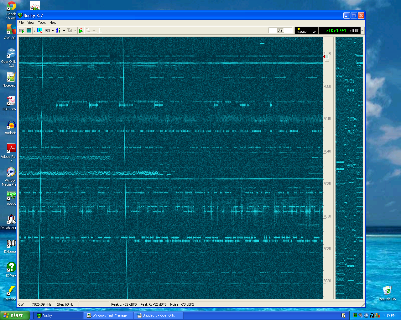
By w4kaz, created on 2012.05.03 at 12:26:02 | last changed on 2012.05.03 at 12:45:01 | After a lot of procrastination, the dormant Softrock v6.2 project became timely. The job was to convert a Softrock v6.2 from its intended IF usage(IF 9.001?) to something a wee more interesting fer the KazShack main op, namely a 40m Softrock v6.2. The WB5RVZ pages are the place to go for build information. A fabulous job of documentation on the many SR permutations.
Turns out, the conversion was fairly simple. As built, there were only 2 component changes, add the RX enable jumper, and add a wire for the second “ring” line output. Oh….also change the crystal. A few resistance and then voltage checks. Use the K2 as frequency meter to check the crystal oscillator frequency, and its F/4 from the divider. (28.220 and 7.055+/-).
Fired off “Rocky”, VE3NEA’s SDR program. Putz around with the settings for Rocky and the sound card….Success! Sweet.
Now the question…….What the heck is this transient!!???!!
So…..the project is not quite complete. There are two full ready to build kits waiting on the sidelines (hat tip to AE5X for noting the availability). Still need to find a suitable enclosure. It also seems like inserting isolation transformers in the line-outs will be worth the time, and maybe the cost. A search on the radio shack site comes up empty for their audio iso xfmr. Mouser or Digikey.
Job one is a nice shielded enclosure, although there are lots of warnings about being wary of creating ground loops. Probably put an isolation transformer and front end protector on the inputs. Separate power source for the SR, and isolation transformer on the lineouts(insulated) to the sound card. Perhaps extra bypass caps on the power supply.
After that is done, maybe the transients will be reduced or eliminated.
Running Rocky on a dual core Pentium D causes the CPU to sometimes spike as high as 7%. Moving the mouse causes more CPU stress than the SDR software causes. Interesting.
Gonna be a lot of fun with this toy. 🙂
Many thanks to W3DQ for the original project package.
By w4kaz, created on 2012.03.23 at 05:42:22 | last changed on 2012.03.23 at 10:44:30 | When I upgraded the dead computer a couple of years back, I stuffed the current machine(Dell Inspiron 545S w/Pentium Dual-core E5300 @ 2.6ghz) with 8GB of RAM, expecting to do some experimentation with running VMware or some such to tinker with PC based VM’s. Â After looking around a bit, other shiny objects attracted more attention. Â So, being easily distractable…..VM’s slipped down the memory hole.
Fast forward to present. Â Looking over at the Oracle VirtualBox website, a bit of light reading showed that a lot of work has been done on their VM software in the last 18months. Â More robust USB support, and a lot of bug fixes. Â Its free for personal use, so give it a shot.
The VirtualBox software itself installed on Windows 7 Â easily. Â Within a few minutes after that, A VM for an Ubuntu Linux partition was ready for the OS install. Â Virtualbox is able to install an OS from an ISO disk image. Â So after a few minutes waiting for the latest Ubuntu 11.10 version to download, the VM was ready to install. Â It took longer to download the ISO than it took VirtualBox to install the OS(unusually slow day for the internet connection to blame there).
The quick summary is that Ubuntu runs well inside the VM sitting on a Windows7 host. Â I expect that the opposite is likely to be a more desirable arrangement, but living in the real world, there it is. Â I expect to use the Ubuntu partition to allow tunneling over to the Linux server box using VNC to control the desktop on the remote server. Â Its possible to set that up using something like TightVNC under windows, but the whole thing is a lot simpler to configure in a Linux to Linux environment. Â The VM runs on the windows desktop just like another windows application. Â Nice and simple.
More complicated hardware interfaces are probably a lot more difficult to configure(if they are possible at all), but outside of some radio control software, I don’t expect to need to delve that deeply. Â I suppose there will be latency issues based on some comments from N4AF, but curiosity may eventually point me in that direction anyway.
Unrelated sidenote, but after installing the 11.10 version of Ubuntu, I immediately ditched the “unity” desktop and reverted to “gnome”. Â Another “Unity = new coke” example? ? ? Â [Comments appreciated on this topic]
A second VM is now set up with a small Windows XP partition using the Windows XP license from the dead desktop.  It turns out that XP was a bit more difficult to install.  The problems were probably due to hardware conflict issues between VirtualBox and the host over the CD-DVD drive.  After ripping  XP to an on-disk ISO, installation made much better progress.
It turns out the XP partition will be handy for running the version of EZNec I have. Â Later versions of EZNec have a 32 bit installer, but the last edition I have is using a 16 bit installer which will not work with 64 bit Windows 7. Â So now EZNec has a home on the desktop again, even if its inside a shell running on top of the shell. Â In fact, the EZNec install on an XP VM runs quite a lot better than I expected – much faster than on a P4 with 1 GB of ram.
So for some select older applications, an XP VM in the VirtualBox world is a viable option.  It’s a kludge, but potentially a very useful kludge.  Another very useful aspect is that the VM’s can be very easily copied.  Useful for backups and migration.  And always having a pristine version saved could be handy.  I’m tempted to start saving pennies for a multicore processor machine with the latest/greatest fast CPU’s and memory, and use a VM for everyday usages.  Also curious if running the VM’s over a Linux host OS ultimately makes more sense.
Latest-n-greatest is wonderful, but I just hate leaving behind programs that work perfectly well. Â CT anyone? Â OK, maybe not….
O’course the bleeding edge crowd will still descend into hysterics over the concept of “continuing to drive the 1984 Honda Civic”, but I figure they have enough cash in their pocket to not be concerned with the trivial expenses involved in their upgrades to all new replacement software.  If it were not just for a  hobby tinkering project, maybe I’d agree.
“Better” is such a subjective concept, aina?
|
|