By w4kaz, created on 2012.05.20 at 16:40:33 | last changed on 2015.04.13 at 12:15:31 |
So….Who will be the first to hack one of these things to use for hauling antenna lines up into trees for Field Day? Â They will be forever honored in the Halls of HamHacks.
A simple solenoid that is remotely activated to pull a pin and drop the line should do the job. Â The challenge is probably finding a solenoid that is light enough to be lifted by the drone when combined with the weight/drag of the line. Â Which leads to the question of “what’s the payload capacity(if any)?”
By w4kaz, created on 2012.05.03 at 12:26:02 | last changed on 2012.05.03 at 12:45:01 |
After a lot of procrastination, the dormant Softrock v6.2 project became timely. The job was to convert a Softrock v6.2 from its intended IF usage(IF 9.001?) to something a wee more interesting fer the KazShack main op, namely a 40m Softrock v6.2. The WB5RVZ pages are the place to go for build information. A fabulous job of documentation on the many SR permutations.
Turns out, the conversion was fairly simple. As built, there were only 2 component changes, add the RX enable jumper, and add a wire for the second “ring” line output. Oh….also change the crystal. A few resistance and then voltage checks. Use the K2 as frequency meter to check the crystal oscillator frequency, and its F/4 from the divider. (28.220 and 7.055+/-).
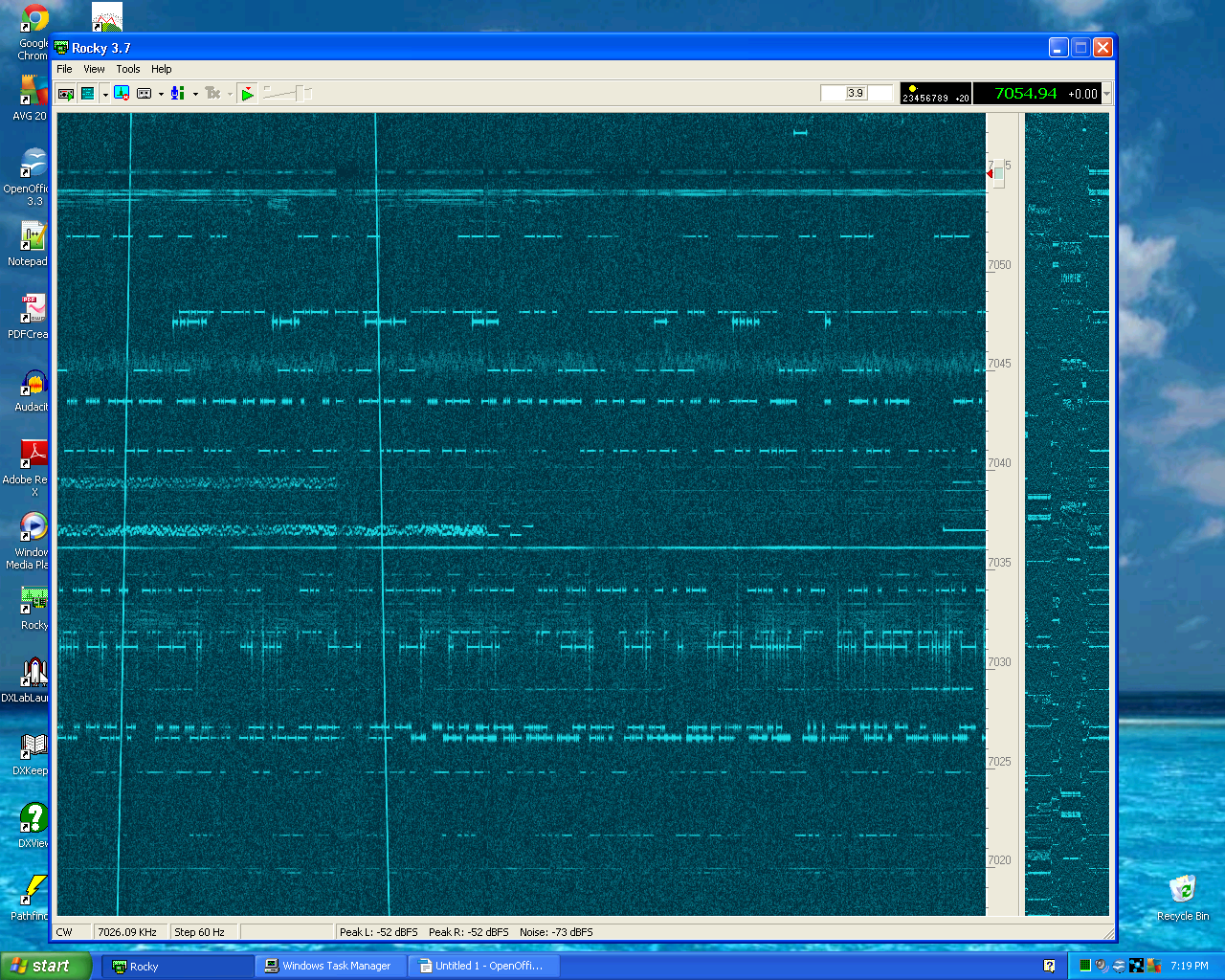
Fired off “Rocky”, VE3NEA’s SDR program. Putz around with the settings for Rocky and the sound card….Success! Sweet.
Now the question…….What the heck is this transient!!???!!
So…..the project is not quite complete. There are two full ready to build kits waiting on the sidelines (hat tip to AE5X for noting the availability). Still need to find a suitable enclosure. It also seems like inserting isolation transformers in the line-outs will be worth the time, and maybe the cost. A search on the radio shack site comes up empty for their audio iso xfmr. Mouser or Digikey.
Job one is a nice shielded enclosure, although there are lots of warnings about being wary of creating ground loops. Probably put an isolation transformer and front end protector on the inputs. Separate power source for the SR, and isolation transformer on the lineouts(insulated) to the sound card. Perhaps extra bypass caps on the power supply.
After that is done, maybe the transients will be reduced or eliminated.
Running Rocky on a dual core Pentium D causes the CPU to sometimes spike as high as 7%. Moving the mouse causes more CPU stress than the SDR software causes. Interesting.
Gonna be a lot of fun with this toy. 🙂
Many thanks to W3DQ for the original project package.
By w4kaz, created on 2012.03.23 at 05:42:22 | last changed on 2012.03.23 at 10:44:30 |
When I upgraded the dead computer a couple of years back, I stuffed the current machine(Dell Inspiron 545S w/Pentium Dual-core E5300 @ 2.6ghz) with 8GB of RAM, expecting to do some experimentation with running VMware or some such to tinker with PC based VM’s. Â After looking around a bit, other shiny objects attracted more attention. Â So, being easily distractable…..VM’s slipped down the memory hole.
Fast forward to present. Â Looking over at the Oracle VirtualBox website, a bit of light reading showed that a lot of work has been done on their VM software in the last 18months. Â More robust USB support, and a lot of bug fixes. Â Its free for personal use, so give it a shot.
The VirtualBox software itself installed on Windows 7 Â easily. Â Within a few minutes after that, A VM for an Ubuntu Linux partition was ready for the OS install. Â Virtualbox is able to install an OS from an ISO disk image. Â So after a few minutes waiting for the latest Ubuntu 11.10 version to download, the VM was ready to install. Â It took longer to download the ISO than it took VirtualBox to install the OS(unusually slow day for the internet connection to blame there).
The quick summary is that Ubuntu runs well inside the VM sitting on a Windows7 host. Â I expect that the opposite is likely to be a more desirable arrangement, but living in the real world, there it is. Â I expect to use the Ubuntu partition to allow tunneling over to the Linux server box using VNC to control the desktop on the remote server. Â Its possible to set that up using something like TightVNC under windows, but the whole thing is a lot simpler to configure in a Linux to Linux environment. Â The VM runs on the windows desktop just like another windows application. Â Nice and simple.
More complicated hardware interfaces are probably a lot more difficult to configure(if they are possible at all), but outside of some radio control software, I don’t expect to need to delve that deeply. Â I suppose there will be latency issues based on some comments from N4AF, but curiosity may eventually point me in that direction anyway.
Unrelated sidenote, but after installing the 11.10 version of Ubuntu, I immediately ditched the “unity” desktop and reverted to “gnome”. Â Another “Unity = new coke” example? ? ? Â [Comments appreciated on this topic]
A second VM is now set up with a small Windows XP partition using the Windows XP license from the dead desktop.  It turns out that XP was a bit more difficult to install.  The problems were probably due to hardware conflict issues between VirtualBox and the host over the CD-DVD drive.  After ripping  XP to an on-disk ISO, installation made much better progress.
It turns out the XP partition will be handy for running the version of EZNec I have. Â Later versions of EZNec have a 32 bit installer, but the last edition I have is using a 16 bit installer which will not work with 64 bit Windows 7. Â So now EZNec has a home on the desktop again, even if its inside a shell running on top of the shell. Â In fact, the EZNec install on an XP VM runs quite a lot better than I expected – much faster than on a P4 with 1 GB of ram.
So for some select older applications, an XP VM in the VirtualBox world is a viable option.  It’s a kludge, but potentially a very useful kludge.  Another very useful aspect is that the VM’s can be very easily copied.  Useful for backups and migration.  And always having a pristine version saved could be handy.  I’m tempted to start saving pennies for a multicore processor machine with the latest/greatest fast CPU’s and memory, and use a VM for everyday usages.  Also curious if running the VM’s over a Linux host OS ultimately makes more sense.
Latest-n-greatest is wonderful, but I just hate leaving behind programs that work perfectly well. Â CT anyone? Â OK, maybe not….
O’course the bleeding edge crowd will still descend into hysterics over the concept of “continuing to drive the 1984 Honda Civic”, but I figure they have enough cash in their pocket to not be concerned with the trivial expenses involved in their upgrades to all new replacement software.  If it were not just for a  hobby tinkering project, maybe I’d agree.
The whole idea of operating on 160m started as curiosity. Before 2005 I had never operated on 160m. Ever. I had listened some, but never keyed the transmitter other than to experiment with arcing capacitors and high levels of SWR. But it generally seemed like it would be fun, so give it a try to find out, right?
After looking at a couple of locations in the yard, it seemed like there just wasn’t enough room to !easily! pull up an inverted-Vee, or other crooked dipole of such unusually large size. Tall trees out-the-wazooo in the yard, but spaced closely, so it is difficult for long pulls. There is an emphasis on easy because it is an important consideration. Any antenna that is a pain in the ass to maintain is more likely to be out of service at any given moment at the KazShack qth.
Where O where does a 160m antenna fit?
There is a great spot for a vertical rise of about 70 feet so that seemed to be the ticket. But verticals have their own downside. Radials – bleh!…Ick!…Ptui! But any antenna is better than no antenna at all, so that’s where we get sucked into 160m madness.
The first preference was a top loaded “T” but the useful supports are not arranged in a good pattern for that choice. There was just no way to stretch out the top-hat of the T.
The supports are arranged in such a way that an inverted-L is the logical choice. So a slightly long inverted L was the winner since it 1) fit into the yard where the trees line up, and 2) lends itself to capacitive matching if made slightly long. The result was an inv-L with the vertical section that goes up 70′, then across 40′, and across again in a different direction for another 50′. Approximately 155′(47m) of wire total length.
That leaves the radials. Buried radials just were not going to happen. Far too many tree roots and stone in the back yard, and no grass at all. What then is the nascent TopBander to do?
The Early years
The first Inv-L install circa 2005 had four elevated radials of equal length, about 37′ each. All were tied together and loaded via a coil at the base of the antenna. No chokes, and no decent matching network.  In this incarnation, antenna performance was poor. Even loud stations were difficult to work. Heard no DX. No surprises there.
The first “improvement” circa 2007 was to add 12 random length radials, a 1.5:1 step down unun(W2FMI design), and a coaxial choke wound from about 70′ of rg-58 wound on a PVC garden pot. The performance improvement, while not quantifiable was immediately noticeable. Stations became easier to work on a single call, and I was now able to detect the whispers of DX stations. A new K9AY for RX was also added to the mix just before these changes to the TX antenna. It also appeared that the improved TX antenna was now hearing most of what could be heard on the K9AY, although the K9Ay has a much lower noise floor and is usually much easier on the ears.
The Intermediate
Radials were added incrementally from 2007 through mid 2010 until there was a total of about 30. The original four 37 footers were the longest, and there were another four that were approximately 27 feet long. Everything else was a mish-mash of random lengths, added in pairs to the available trees in the area. Somewhere along the line(2008) I also added the capacitors required to get a good match at the base of the antenna, and have a nice low SWR both at the antenna base and at the shack-end of the feed line. And the nice narrow SWR bandwidth that accompanies such.
Performance of the final well-matched radial version of 2010 seemed to be quite good in comparison to the earliest version. In 2009 and 2010 it was possible to run stations(low power) in the 160m contests, and Q’s were made more often with the western US, as well as a handful of DX stations.
Before any other changes were made, I took some signal strength measurements in late 2011 using the K2 as field-strength meter, with the FT-920 as transmitter. The test configuration was 1) transmit full power from the FT-920 on the TX antenna at its lowest SWR point, 2)RX on the K2, using a dummy load at the end of a 7 foot jumper cable. dummy load hanging off edge of desk. K2 attenuator on, rf gain at max.
Using that configuration:
100w into the transmit antenna produces S-5 on K2 S-meter
100w into separate dummy load produces audible S-zero on K2 S-meter
As poor as it is, that reading is the best actual measurement available, from what in my opinion was the best of the radial configurations. Taken in early December 2011.
Decision Time
In 2009-2010, K2AV began discussing an idea he had for solving the small-lot-on-160m problem. Based on his modeling and studies of ground losses, he reasoned that a single counterpoise might be a solution that would work for space limited locations. He determined that a counterpoise that was 5/16th wavelengths might show useful current cancellations if it were strategically folded, to help with the problem of ground losses. So evolved the “5/16th wave folded counterpoise”, now being generally referred to as “516 FCP” or just as “an FCP” . The idea seemed to have a lot of merit, but being a serial procrastinator it took some time for me to get off my hindquarters and make the changes to try it out.
In early 2011, K2AV gave me one of his isolation transformers, as well as an inductor. Their implementations of the FCP at K2AV’s and W0UCE’s qth required additional inductance for matching(hence the inductor). They also discovered that the isolation transformer was a necessity to obtain good field strength results. The transformer design is beefy enough to handle their high power operations.  The design of the FCP has gone through some evolutions/refinements, and the design K2Av is recommending was originally field tested at his own qth in the 2011 CQ160m CW contest with low power, and with excellent results.
K2AV style FCP System Installed
My own original intent was to install his isolation transformer into my original system and transition to the FCP. Curiosity compels me to wonder what sort of improvement the isolation transformer might have provided on its own in the old system. That test never happened, but it is really just a matter of curiosity. It would still be good to know if the transformer would have made an improvement in signal with the radial jumble. I expect the choking on the radial system was less than ideal, far less than what was necessary, and the system probably was subject to higher losses because of that. That transition never happened, so I missed having the new system ready for ARRL DX. Impatience won out when an opportunity to do the work came up.
In the week after ARRL DX, the radials/coil were removed and K2AV’s folded counterpoise and isolation transformer were added to the antenna. [NEW link: K2AV FCP home page] A new junction box was built to house the isolation transformer and matching network. K2AV came by with his analyzer, and we spent a morning giving the system a look-see. As it turns out, the same value of matching capacitors were suitable for use without modification, and the inductor was not required because my inv-L is long. Matching the system was as simple as adding capacitance until a match was found. A large value air variable could be used to find the required match in less than five minutes, then replaced with capacitors suitable for handling the currents.
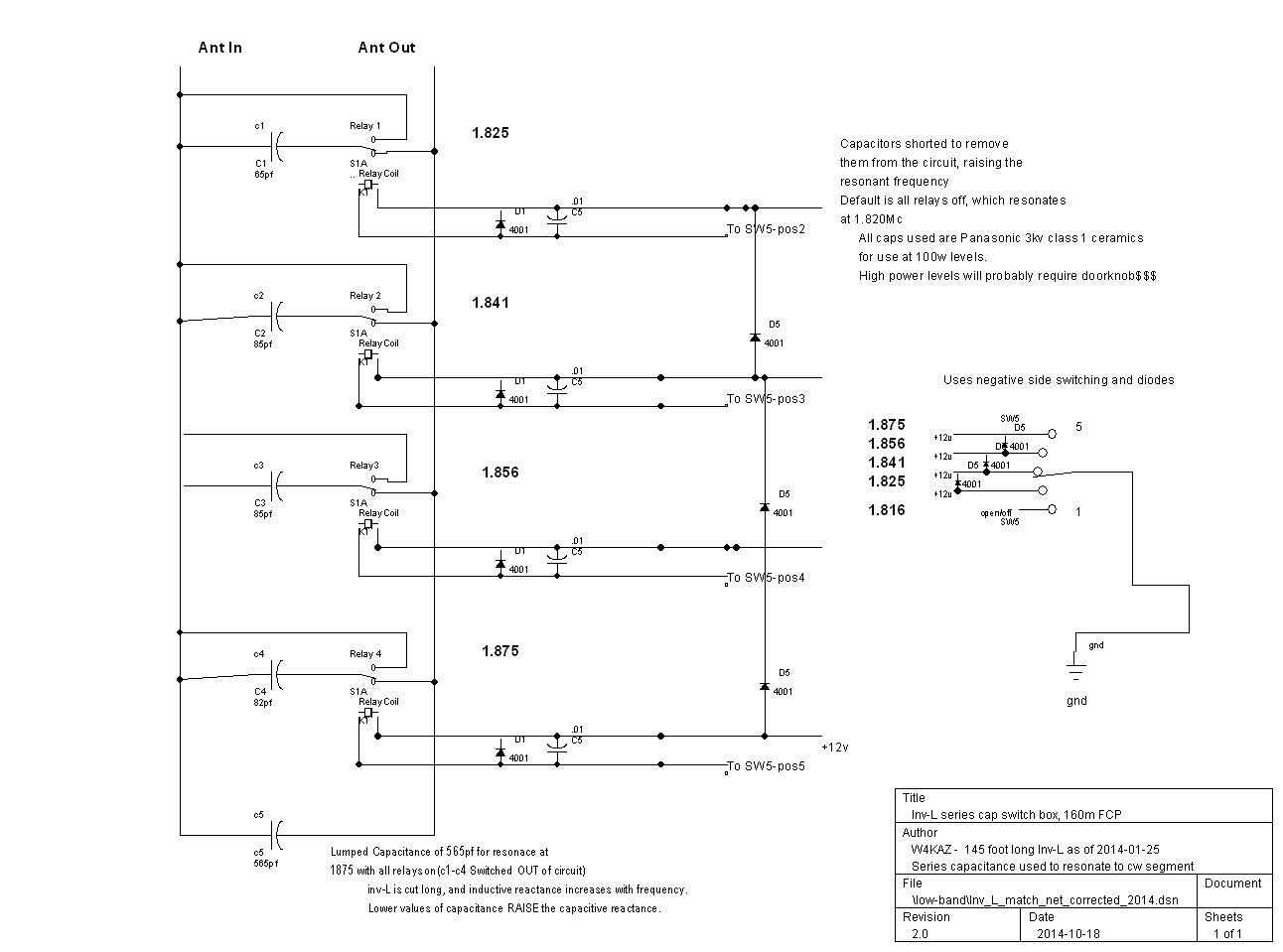
My own matching network is a group of HV ceramic caps in parallel[Obsolete, probably unavailable, 2016/09/25]. These are mounted on a board that allows switching some of the capacitance out to move the resonance up the band. The switch board will also allow switching to a different vertical element, but that feature won’t be useful without also switching the FCP. The FCP is a mono-band solution.
Schematic for W4KAZ 160m inverted L with K2AV FCP
Picture of W4KAZ 160m matching network and transformer junction box in use with 155 foot long inverted L and K2AV FCP
The Present….So, What of it?
The system now up is the same/original inverted-l vertical section with the K2AV folded counterpoise and isolation transformer in place of the prior elevated radial jumble. What happened?
Using the K2 as field strength meter again, and using the exact same conditions as described above(sense antenna dummy load hanging from desk on 7 foot jumper):
20w into the antenna from FT-920 now registers S5 on K2 S-meter
40w into the antenna from FT-920 now registers S5 plus one bar on K2 S-meter
60w into the antenna from FT-920 now registers S5 plus two bars K2 S-meter
100w into the antenna from FT-920 now registers S9 (S5 plus three bars)
100w into separate dummy load produces audible S-zero on K2
The S-meter on this K2 is not calibrated in real world db, but even without knowing exact values the signal is obviously stronger than it was with the previous TX antenna system. Yes, that’s in the near field, but still it is encouraging.
The first field test was during 2011 Stew Perry. Anecdotally, I was very happy with antenna performance. It really seemed like I was louder, and it seemed I got fewer requests for fills. But the time for a full effort wasn’t there, so there is just a limited amount of data. Not too shabby for just three hours of operating.
A better sample was taken during the 2012 CQ 160m CW. (And here.) A total of 20 hours was operated. Terrible propagation conditions.  The first 6 or so hours were very good compared to previous 160m contests. 20 total hours of operation produced 593 QSO’s. Even with terrible conditions, I was able to work a couple of EU stations. Low Power. Not as good as K2AV in 2011, but one hell of a lot better than I anticipated, especially in poor conditions. K2AV is also a much better CW op, so I doubt I’ll ever be able to hit that 925 Q milestone.
So I’m pretty happy with the current system incorporating both the FCP and isolation transformer. Many thanks to K2AV!
W4KAZ Construction Variance Notes
In implementing the FCP design at the KazShack, I made a few variances from the recommendations.
The FCP itself is constructed of stranded 14ga hardware store THHN. I like the flexibility of the wire, the sturdy insulation, and most important, I have several rolls of it already bought and paid for.
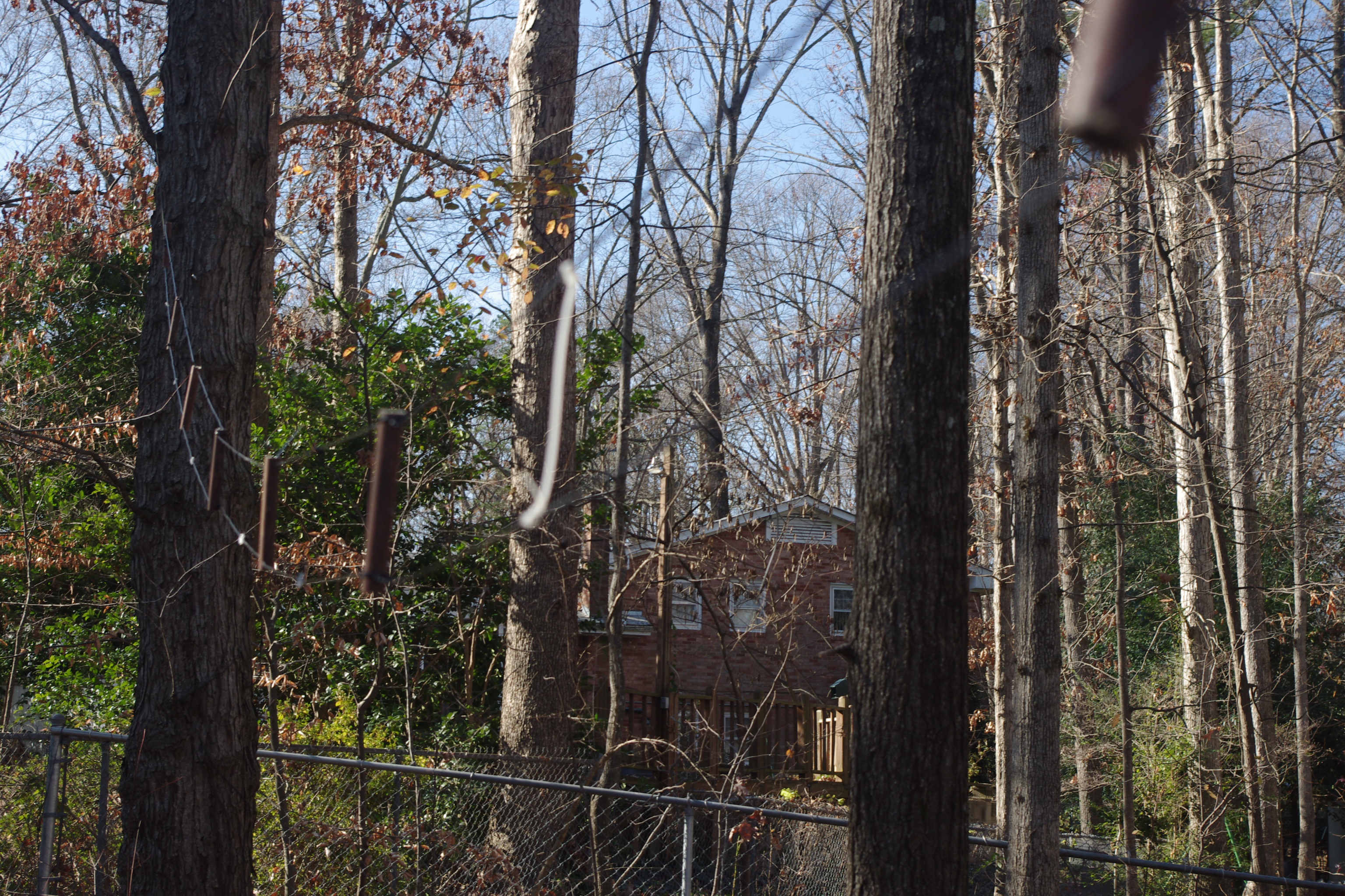
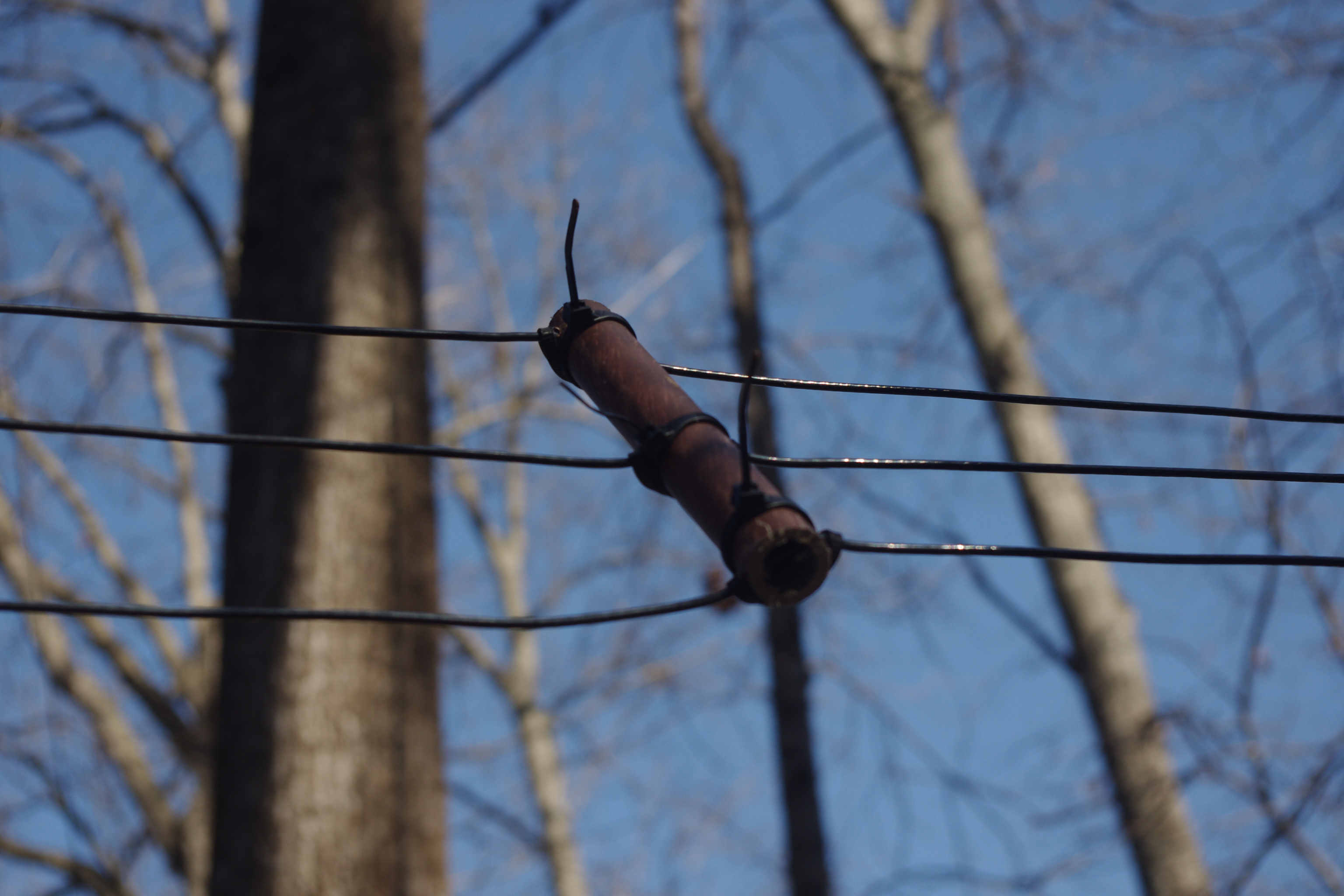
The FCP insulators were cut from an unused piece of PVC electrical conduit. That was also what happened to be at hand in the form of spreaders from an experiment with hex-beams. From the length of PVC available for the job, I cut 16 spacers of 6 inches length(~150mm). Each was drilled through three times, a hole in the center, and one about .5 inches from each end. On the leg with two wires, the spacing is about 5 inches(125mm), while on the leg with three conductors the spacing is only ~2.5 inches(~60mm). The holes are intentionally mis-aligned or drilled at offset angles.   That allows the wire itself to place tension on the spreader to keep the spreaders in place. This method makes it easy to do with an ordinary hand drill – being crooked is an advantage. :)  The mis-alignment alone is not enough to keep the spreaders from sliding, so they are also wrapped with vinyl cable ties as needed. The distance between each spacer works out to about 4 feet(~1.3m). Vinyl cable ties are also used as spacers at the midpoint between each PVC spacer.
Measuring and threading the wire was the most time consuming part of the FCP construction. Because all of the separators are of equal size and drilled the same the side of the FCP with three conductors is more closely spaced than the side with two. This made mechanical construction very easy, the FCP is taut and sturdy, and does not seem to have any adverse effects on basic function.
The transformer and matching network is installed in a nice hamfest/surplus telco box, about 8x8x4. This is a nice weather tight enclosure. The transformer is exact to K2AV specs(by definition – it was wound by K2AV his-self!). The matching network of switched parallel caps is scavenged from the old weather enclosure(a sealed PVC pipe) and re-used in the new junction box. These components fit well enough, but there would not have been space to house the additional toroidal inductor had it been needed.
Besides the apparent signal improvements over the rejected-random-raised-radial-rambling-razzledazzle, the FCP itself has other very practical mechanical merits and advantages over raised radials.
The folded counterpoise is simple to build.
The FCP is relatively small, 32′ per side(64′ total length)
The FCP is a LOT easier to deploy than 30 elevated radials, or burying a dense radial mat
The FCP lends itself to following contours, and models well when the FCP is not perfectly straight
The FCP will require a lot less maintenance. The odds of falling branches breaking the FCP here at the home QTH are lower by a factor of 15. (2 legs of FCP vs 30+ radials in 30+ directions, all below branch shedding trees)
all of the above….. !! yipeee!!
Bottom Line…..
But Kaz, is it equivalent to a full size vertical with a dense mat of radials? Probably not, but there is absolutely zero chance that sort of system can ever be installed at this QTH, so the point is moot. Do I care? Nope, it “works”, and it “works” better than it’s predecessor 160m antenna systems AT THIS QTH. Very possible/likely that improvement is just a testimony to the poor performance of the prior system. But better is “better”. Is it snake oil? Probably not, at least not according to the CW skimmer robots, the results K2AV has had with his system, and more important, my own field testing during the CQ160m contest. W8JI has done some comparisons of models. But since they are comparisons to antennas that will not be practical at W4KAZ location, it is academic info. For use here it is about the footprint and 80 foot radials are simply not practical HERE.
2021-03-14 Notation….Nothing Changed
At this point, my only regret is an academic point – not having run the test of inserting the isolation transformer into the old system with the radial-jumble.  The sharp tuning of most 160m antennas suggests that common mode currents will often be a problem as one tunes away from the antenna’s resonance and the reactance increases.   How much benefit is gained from either the isolation transformer or the FCP individually is unknown(to me), but still of both practical and academic interest. I’d really like to know if the old system would have been improved with the isolation transformer installed. Still of interest, but not enough for me to spend time hanging the radials back up again! ;)  Together, the FCP and transformer seem to do a damn fine job here. Certainly the best system that has been active in this location.
What next? FCP phased verticals…..FCP foursquares…..FCP parasitic arrays….. MANY possibilities - if only I had the room to do it.
By w4kaz, created on 2012.01.29 at 15:50:21 | last changed on 2016.08.26 at 20:33:44 |
Grinding out Saturday night with low rates…Yuck.  Worked more stations from the western US, but not a lot. The path down into TX was much better Friday night, but N/S up and down the east coast was decent on Saturday. New England(ME,VT,NH) probably was not as strong as Saturday, but most were workable. Although I guess I didn’t hear the ones that were not. 😮
Can’t remember working so many NY stations. Condx to NY/PA were really good both nights, and lots of NY stations active.
DX was mostly non-existent at the KazShack. The stations that could be heard had large pile-ups – not really worth the effort. With that as a baseline, I did get 11 DX mults. A couple of DL’s could hear me, a loud EI with no pile-up, and a few from the Caribbean.
At some point early on I had set 500 Q’s as a mental goal, despite being determined to not really set goals. Half way there 600 seem like a loftier perch to shoot for. So I was shooting for 500 by midnight. The rate was steady, so it seemed possible. Came up only 6 short, 593 logged by midnight. So hitting 600 seemed possible too.
“Missed it by THAT much”
Well, did not get to 600 Q’s. Took a 2 hour nap and got up for a bit of Butt-In-Chair pre-sunrise. Picked up a few more, but just not enough. West coast never really showed up for me.  Decided to end the effort when I had 20 hours Butt-In-Chair according to the logging program. That happened at QSO#593 an hour after sunrise, with the rate down in the mid teens. Grasp Plug Firmly….Pull. Have other stuff to do late Sunday afternoon/evening, needed some rest.
The Good:
Quick and dirty switch cable hack for the antenna matching network worked well, especially since I spent a lot of time in the 1840-1850’s running. Perfect 1:1 match at either 1818 or 1844 and the K2 Tuner handles about 25 kc on either side of either spot easily. The end game there is probably three positions, with the third match tuned for 1870 to 1880.
Not much S&P, but very few stations asked for repeats and fills. Most could hear me on first call.
N4YDU not operating, but encouraging me to grind it out. tnx!
Kept right on logging Q’s through the LIDS. {“Gentleman’s Band”? – my hairy fat ass.} More evidence the TX antenna mods are working. Had trouble holding 160m runs in CQ160 before. 🙂
Both nights RX here was much better on the K9AY, a 4 S-unit difference in noise levels
The Bad:
Murphy arrived in prankster mode.
Condx not as good as last year. Saturday night better than Friday- less storm static/QRN on Saturday.
Those last 93 Q’s were work.
Muffed my Q with K4BAI again. Its like a tradition now. 🙁
75m spam lids now on TopBand too.
The Ugly:
The K2 blew two fuses, but it appears to be related to rx antenna switching while the K2 is in xmit. Need to run down the wiring and power supply connections. Solution: Stop Switching While CQing!! (K2 is drawing only 15 amps on xmit, something must be causing it to spike.)
DatsDaFaxJack:
Call: W4KAZ
Class: Single Op LP             QTH: NC
Operating Time (hrs): 20

Summary:
Total:  QSOs = 593  State/Prov = 50  Countries = 11  Total Score = 82,960
By w4kaz, created on 2012.01.28 at 14:16:24 | last changed on 2012.01.29 at 14:16:39 |
Well, going back to the salt mine after 1:00an local proved to be a waste of time. Conditions had not improved to areas in the Western US/Canada….or to anywhere else.
Actually, the QRN was lower, and the 8’s and 9’s were louder, as well as stations from AL, GA and FL. There just were not enough callers to justify Butt-In-Chair.
Set the clock for a couple of hours with the hope of getting the early risers….NOT. Slept right through the alarm, so Saturday morning was lost.
By w4kaz, created on 2012.01.28 at 01:40:04 | last changed on 2012.01.28 at 01:40:04 |
Not too shabby. After 6.0 hours of operation, 270 Q’s in the log. Not much in the Western US, but have CA and AZ. Spent the first 30 minutes S&P, then a couple of short runs, another stretch of S&P, and then a nice steady run. Nothing fabulous, but the Inv-L is playing much better than is has in the past.
Early in the evening, the K9AY was the best on RX. The QRN has slowly been tapering off, so RX on the Inv-L is better. The K9AY still has the edge – when it happens to be pointing in the correct direction.
Blew two fuses in the power line to the K2. Both blew when switching the RX antenna during xmit. Must be causing a voltage spike. Solution: Don’t Do That!
So far the anecdotal evidence indicates I’m being heard better with the changes to the TX antenna. Gonna save looking at the RBN spots for Sunday.
By w4kaz, created on 2012.01.27 at 18:05:45 | last changed on 2012.01.27 at 18:05:45 |
Getting the last minute woolgathering in before the contest begins.
Made a last-minute antenna mod to the Inv-L with K2AV FCP. The antenna matching network has been ready for switching out matching capacitors for over a year. The missing piece has been a control box and control cable to the feedpoint. After a bit of consideration of solving this issue before the contest, the brain caught up and realized an interim solution was already in place.
When the Sixpak was added to the antenna system a couple of years back, the existing seven position switch was pressed into ‘temporary’ service as an A/B switch for a pair of 40m dipoles. But they occupy positions 1 & 2 on the switch.
So why not use the other switch positions to serve double duty? The switch is about ten feet from the base of the 160m antenna, so its a short run of control cable versus the 80 run needed back to the shack.
So as a quick and dirty solution, I hacked together a plug to mate to the switch control line. Just plug the 160m switch into the control cable for the seven position switch.
Presto-change-o. Now I can move the best match on 160m from 1820 up to 1845. Sufficient for a CW contest, although 1855 would be ideal. More tweaking needed, but better.
Goals for the weekend are more or less to lay down a good set of spots into the Reverse Beacon Network. No real QSO goals. Try to maximize time spent running, and try to do it over two nights.
By w4kaz, created on 2012.01.22 at 17:51:14 | last changed on 2012.01.22 at 16:56:02 |
DAMN that was a GOOD contest.
N1LN hosted the M/2 operation as NC4KW for both CW and SSB. This years SSB team was N1LN, N4GU, N4YDU, and W4KAZ.
N4YDU led off on the right hand station on 10m. W4KAZ squatted on 20m a few minutes before contest kick off, and worked a few before the start of the contest. When the contest started, it was off to the races. The end of the first hour showed a nice total of around 170 Q’s. 10m was slower than 20m, but N4YDU scrounged a nice group of multipliers before dropping down to 15m. Rates for the second hour took off, and stayed good for the next eight hours. Just lots of fun.
20m conditions seemed very good, and that’s where I did the bulk of my operating. The rates on 15m and 40m were also very steady – N4YDU and N4GU made the most of it. They did a lot of the heavy lifting with band changes and mult hunting on the right hand station. N1LN and I swapped off shifts on the left station, and spent the first six hours on 20m. At the start of his second shift, 20m was really drying up. N1LN dropped down to 80m. 80m was noisy, and the rates were slow at the beginning. It warmed up towards the end of N1LN’s shift, and the rates soon were very good there. N4GU and N4YDU had 40m smoking by then, and were keeping the rate meter busy.
Towards the middle of the last shift, N4YDU on 40m and me on 80m, the 60 minute rate got close to 200. Almost, but not quite there.
Damn – THAT was a GOOD contest!
The 80m results were good, but conditions there were fairly difficult. There were loud static crashes to the south of our QTH. It was difficult copy doing RX on the TX antenna. Using the beverages, stations were calling from all directions, so it was difficult to copy the calls on the first try. Towards the end of my last shift, it seemed the best compromise for my ears was to use the beverages for RX with the K3’s pre-amp on and the RF gain turned back, and a hand constantly riding the beverage selection knob and sometimes the RF gain.  Static crashes still made copy difficult on stations to the west. The west beverage was needed for copy on stations from TX to IA and all points beyond and between, but it was also getting a lot of the storm static from the south.  VE stations were solid copy as long as the correct beverage was selected – which was seldom the case.
Damn – that was a GOOOOOD contest!
The two shifts I pulled on 20m were very good, and probably the best I have had as an op at N1LN. Signals were generally solid copy. QRN was relatively low. The QRM was manageable, probably because activity was spread out up to 10m. Rates were very steady. I did find that the occasional nudge to the antenna direction often produced a new flurry of Q’s to pop in for a visit to our log. Swinging back and forth from TX to NNW was the plan of action. The occasional NE station was often loud enough to copy easily off the edges, but pointing either of the antennas directly NE produced little. 20m did not seem to “go short” as it did for me when operating NAQP CW from home. It just seemed to die.
The final tally shows a good spread of Q’s across the bands.
The Good
great team
great station
good high band conditions
K3 Protective circuit works!(see “the ugly”)
N1LN 10 minute repair service – Priceless!
The Bad
low band noise was high
Hardware issue cut into N4YDU 15m rate
The Ugly
The left station K3 folded back to 5w during the second hour in the middle of N4YDU 15m run. Cooling fans not running, so heat sensor cut amp off. Loose fan cable. Repair by N1LN.
By w4kaz, created on 2012.01.20 at 06:48:47 | last changed on 2012.01.19 at 12:11:53 |
One of the things that kept me away from the keyboard was a woodwork project idea.
Several years back, I saw a design for a compact kitchen/breakfast table. The tabletop folded over to convert the table into a bench. The basic idea was used to build two outdoor tables of similar design. They are very functional, but a bit heavy. One is in daily use as a catch all work table. The other slightly larger table is on the backyard patio and is used with the tabletop grill.
The eldest son moved to an off campus apartment which has a large deck. It seemed like a good place for a similar table. So it was time to pencil out a new design that I could put together for an updated “new and improved” version. Several years of use had made some of the shortcomings of the original tables obvious. The “new” ideas are that: 1) it needed to fit into the car for transport, and 2) should be made of lighter weight materials to generally make it easier to move around. This is what popped out…….
First attempt at picnic table bench
Not a terribly good photo, but there are a few more coming.
The table has four components: 2 sides, the top, and the bench. The sides are simply bolted to the bench with 1/4 inch carriage bolts, while the top rests on top of the top arms of the side pieces. The top is simply pinned into place using 1/4 inch J bolts. The top itself is formed from boards attached to ribs with deck screws, all countersunk from below keeping the tabletop unblemished.  The table top hinges over on the rear pair of J-bolts to become the backrest for the bench. Pictures are better….
Picnic table with top folded back as bench.
The materials used are all pressure treated pine lumber. To give the surfaces a bit of a protective finish, the table top got four or five coats of good old-fashioned pure tung oil, which incidentally has become difficult to find. I like tung oil – it is more resistant to mold and mildew, so is better for an outdoor application than boiled linseed oil, and I expect it to hold up in the mountain UV sunlight a lot better than a polyurethane. After its dried, tung oil is also resistant to alcohol and related solvents. Good stuff. I suppose it has fallen from favor because of the rise in popularity of the polyurethanes, and the substitution of the less expensive boiled linseed oil finishes. It was also a bit of an experiment, as none of the other normal finishes are worth a flying-*#%^ on pressure treated lumber, whereas tung oil does a better job on this material and is non-toxic, unlike oils designed for treating pressure treated decks.
So the table top and bench have a nice hand buffed tung oil finish. Its difficult to tell in these photos, but that experiment was proven to be effective.
The back of the bench
As it turns out, the selection of pressure treated that happened to be in the bin at the big-box-lumber-retailer included several nice heart-pine crosscuts, which had nice colored grain detail. The coloration was enhanced by the oil finish. It really looks a lot better than I expected. Almost kept this one and made a second table for NumberOneSon. 😮
side view of bench attachment to side arms
Inside/underside view of bench attachment to side arm
The problem areas in the design relate to the hinging of the table top and its use as a seat back. The sides of the table are made from deck ballusters. I’ve found that these are generally cut from knot free sections of clear even-grained wood, and are quite strong. Also relatively inexpensive. So the side sections are held together with deck screws and waterproof polyurethane exterior construction adhesive. The top rail may not be strong enough for the hinge, and may eventually need a re-inforcement of steel or aluminum added.
Also, the original benches had wider sides, which served to “stop” the bench top fold over at just over 90 degree seat back angle. Solving that problem on this new bench did not occur to me until it became clear the sides here will allow the top to hinge over well past a comfortable seat-back angle. So the kludge to remedy that design flaw was a simple chunk of balluster attached at angle on the inside of the sides. It helps add rigidity to the sides as well as acting as a bumper for the table top when hinged over as a seat.
Side view of table with top hinged over for use as bench
Just right for soaking up a bit of mountain sunshine – and hopefully the moonshine won’t eat away the finish.


