Radio W4KAZ Thanks for stopping by the virtual KazShack. Feel free to comment - I often approve them.
|
By w4kaz, created on 2012.02.25 at 20:16:52 | last changed on 2021.07.01 at 08:59:23 | Saga of transitioning to K2AV’s FCP(folded counterpoise)
(Updated 03/13/2021 de w4kaz, add/edit links and link to newer K2AV FCP page)Â Â NOTE: Please use this K2AV link for most current construction info
TopBand? Wazzat?
A saga of switching from raised radials to a version of the K2AV FCP for a 160m inverted-L.
The whole idea of operating on 160m started as curiosity. Before 2005 I had never operated on 160m. Ever. I had listened some, but never keyed the transmitter other than to experiment with arcing capacitors and high levels of SWR. But it generally seemed like it would be fun, so give it a try to find out, right?
After looking at a couple of locations in the yard, it seemed like there just wasn’t enough room to !easily! pull up an inverted-Vee, or other crooked dipole of such unusually large size. Tall trees out-the-wazooo in the yard, but spaced closely, so it is difficult for long pulls. There is an emphasis on easy because it is an important consideration. Any antenna that is a pain in the ass to maintain is more likely to be out of service at any given moment at the KazShack qth.
Where O where does a 160m antenna fit?
There is a great spot for a vertical rise of about 70 feet so that seemed to be the ticket. But verticals have their own downside. Radials – bleh!…Ick!…Ptui! But any antenna is better than no antenna at all, so that’s where we get sucked into 160m madness.
The first preference was a top loaded “T” but the useful supports are not arranged in a good pattern for that choice. There was just no way to stretch out the top-hat of the T.
The supports are arranged in such a way that an inverted-L is the logical choice. So a slightly long inverted L was the winner since it 1) fit into the yard where the trees line up, and 2) lends itself to capacitive matching if made slightly long. The result was an inv-L with the vertical section that goes up 70′, then across 40′, and across again in a different direction for another 50′. Approximately 155′(47m) of wire total length.
That leaves the radials. Buried radials just were not going to happen. Far too many tree roots and stone in the back yard, and no grass at all. What then is the nascent TopBander to do?
The Early years
The first Inv-L install circa 2005 had four elevated radials of equal length, about 37′ each. All were tied together and loaded via a coil at the base of the antenna. No chokes, and no decent matching network.  In this incarnation, antenna performance was poor. Even loud stations were difficult to work. Heard no DX. No surprises there.
The first “improvement” circa 2007 was to add 12 random length radials, a 1.5:1 step down unun(W2FMI design), and a coaxial choke wound from about 70′ of rg-58 wound on a PVC garden pot. The performance improvement, while not quantifiable was immediately noticeable. Stations became easier to work on a single call, and I was now able to detect the whispers of DX stations. A new K9AY for RX was also added to the mix just before these changes to the TX antenna. It also appeared that the improved TX antenna was now hearing most of what could be heard on the K9AY, although the K9Ay has a much lower noise floor and is usually much easier on the ears.
The Intermediate
Radials were added incrementally from 2007 through mid 2010 until there was a total of about 30. The original four 37 footers were the longest, and there were another four that were approximately 27 feet long. Everything else was a mish-mash of random lengths, added in pairs to the available trees in the area. Somewhere along the line(2008) I also added the capacitors required to get a good match at the base of the antenna, and have a nice low SWR both at the antenna base and at the shack-end of the feed line. And the nice narrow SWR bandwidth that accompanies such.
Performance of the final well-matched radial version of 2010 seemed to be quite good in comparison to the earliest version. In 2009 and 2010 it was possible to run stations(low power) in the 160m contests, and Q’s were made more often with the western US, as well as a handful of DX stations.
Before any other changes were made, I took some signal strength measurements in late 2011 using the K2 as field-strength meter, with the FT-920 as transmitter. The test configuration was 1) transmit full power from the FT-920 on the TX antenna at its lowest SWR point, 2)RX on the K2, using a dummy load at the end of a 7 foot jumper cable. dummy load hanging off edge of desk. K2 attenuator on, rf gain at max.
Using that configuration:
- 100w into the transmit antenna produces S-5 on K2 S-meter
- 100w into separate dummy load produces audible S-zero on K2 S-meter
As poor as it is, that reading is the best actual measurement available, from what in my opinion was the best of the radial configurations. Taken in early December 2011.
Decision Time
In 2009-2010, K2AV began discussing an idea he had for solving the small-lot-on-160m problem. Based on his modeling and studies of ground losses, he reasoned that a single counterpoise might be a solution that would work for space limited locations. He determined that a counterpoise that was 5/16th wavelengths might show useful current cancellations if it were strategically folded, to help with the problem of ground losses. So evolved the “5/16th wave folded counterpoise”, now being generally referred to as “516 FCP” or just as “an FCP” . The idea seemed to have a lot of merit, but being a serial procrastinator it took some time for me to get off my hindquarters and make the changes to try it out.
In early 2011, K2AV gave me one of his isolation transformers, as well as an inductor. Their implementations of the FCP at K2AV’s and W0UCE’s qth required additional inductance for matching(hence the inductor). They also discovered that the isolation transformer was a necessity to obtain good field strength results. The transformer design is beefy enough to handle their high power operations.  The design of the FCP has gone through some evolutions/refinements, and the design K2Av is recommending was originally field tested at his own qth in the 2011 CQ160m CW contest with low power, and with excellent results.
K2AV style FCP System Installed
My own original intent was to install his isolation transformer into my original system and transition to the FCP. Curiosity compels me to wonder what sort of improvement the isolation transformer might have provided on its own in the old system. That test never happened, but it is really just a matter of curiosity. It would still be good to know if the transformer would have made an improvement in signal with the radial jumble. I expect the choking on the radial system was less than ideal, far less than what was necessary, and the system probably was subject to higher losses because of that. That transition never happened, so I missed having the new system ready for ARRL DX. Impatience won out when an opportunity to do the work came up.
In the week after ARRL DX, the radials/coil were removed and K2AV’s folded counterpoise and isolation transformer were added to the antenna. [NEW link: K2AV FCP home page] A new junction box was built to house the isolation transformer and matching network. K2AV came by with his analyzer, and we spent a morning giving the system a look-see. As it turns out, the same value of matching capacitors were suitable for use without modification, and the inductor was not required because my inv-L is long. Matching the system was as simple as adding capacitance until a match was found. A large value air variable could be used to find the required match in less than five minutes, then replaced with capacitors suitable for handling the currents.
My own matching network is a group of HV ceramic caps in parallel[Obsolete, probably unavailable, 2016/09/25]. These are mounted on a board that allows switching some of the capacitance out to move the resonance up the band. The switch board will also allow switching to a different vertical element, but that feature won’t be useful without also switching the FCP. The FCP is a mono-band solution.
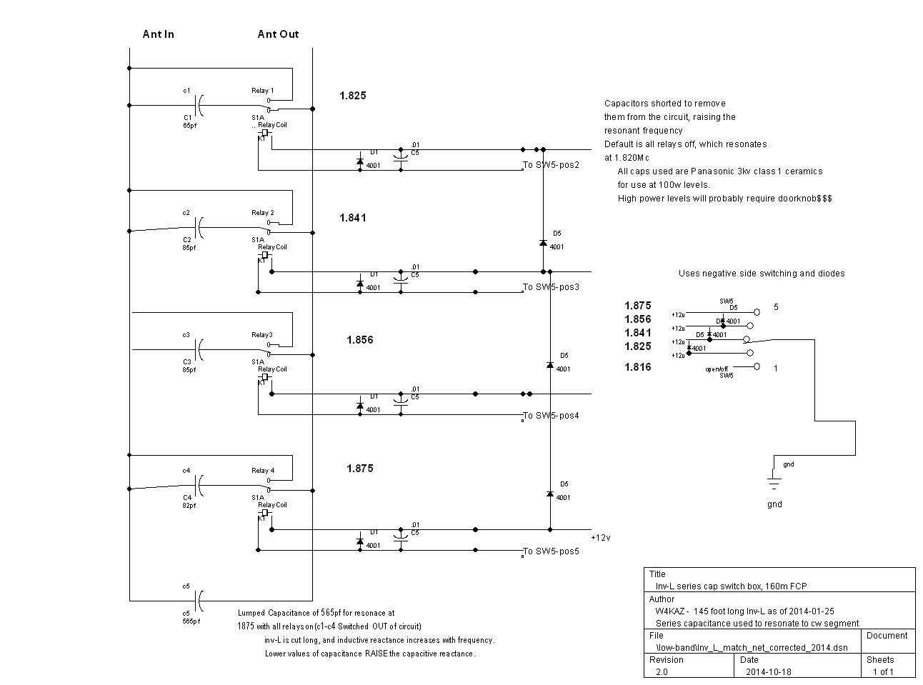
 Schematic for W4KAZ 160m inverted L with K2AV FCP  Picture of W4KAZ 160m matching network and transformer junction box in use with 155 foot long inverted L and K2AV FCP The Present….So, What of it?
The system now up is the same/original inverted-l vertical section with the K2AV folded counterpoise and isolation transformer in place of the prior elevated radial jumble. What happened?
Using the K2 as field strength meter again, and using the exact same conditions as described above(sense antenna dummy load hanging from desk on 7 foot jumper):
- 20w into the antenna from FT-920 now registers S5 on K2 S-meter
- 40w into the antenna from FT-920 now registers S5 plus one bar on K2 S-meter
- 60w into the antenna from FT-920 now registers S5 plus two bars K2 S-meter
- 100w into the antenna from FT-920 now registers S9 (S5 plus three bars)
- 100w into separate dummy load produces audible S-zero on K2
The S-meter on this K2 is not calibrated in real world db, but even without knowing exact values the signal is obviously stronger than it was with the previous TX antenna system. Yes, that’s in the near field, but still it is encouraging.
The first field test was during 2011 Stew Perry. Anecdotally, I was very happy with antenna performance. It really seemed like I was louder, and it seemed I got fewer requests for fills. But the time for a full effort wasn’t there, so there is just a limited amount of data. Not too shabby for just three hours of operating.
A better sample was taken during the 2012 CQ 160m CW. (And here.) A total of 20 hours was operated. Terrible propagation conditions.  The first 6 or so hours were very good compared to previous 160m contests. 20 total hours of operation produced 593 QSO’s. Even with terrible conditions, I was able to work a couple of EU stations. Low Power. Not as good as K2AV in 2011, but one hell of a lot better than I anticipated, especially in poor conditions. K2AV is also a much better CW op, so I doubt I’ll ever be able to hit that 925 Q milestone.
So I’m pretty happy with the current system incorporating both the FCP and isolation transformer. Many thanks to K2AV!
W4KAZ Construction Variance Notes
In implementing the FCP design at the KazShack, I made a few variances from the recommendations.
The FCP itself is constructed of stranded 14ga hardware store THHN. I like the flexibility of the wire, the sturdy insulation, and most important, I have several rolls of it already bought and paid for.
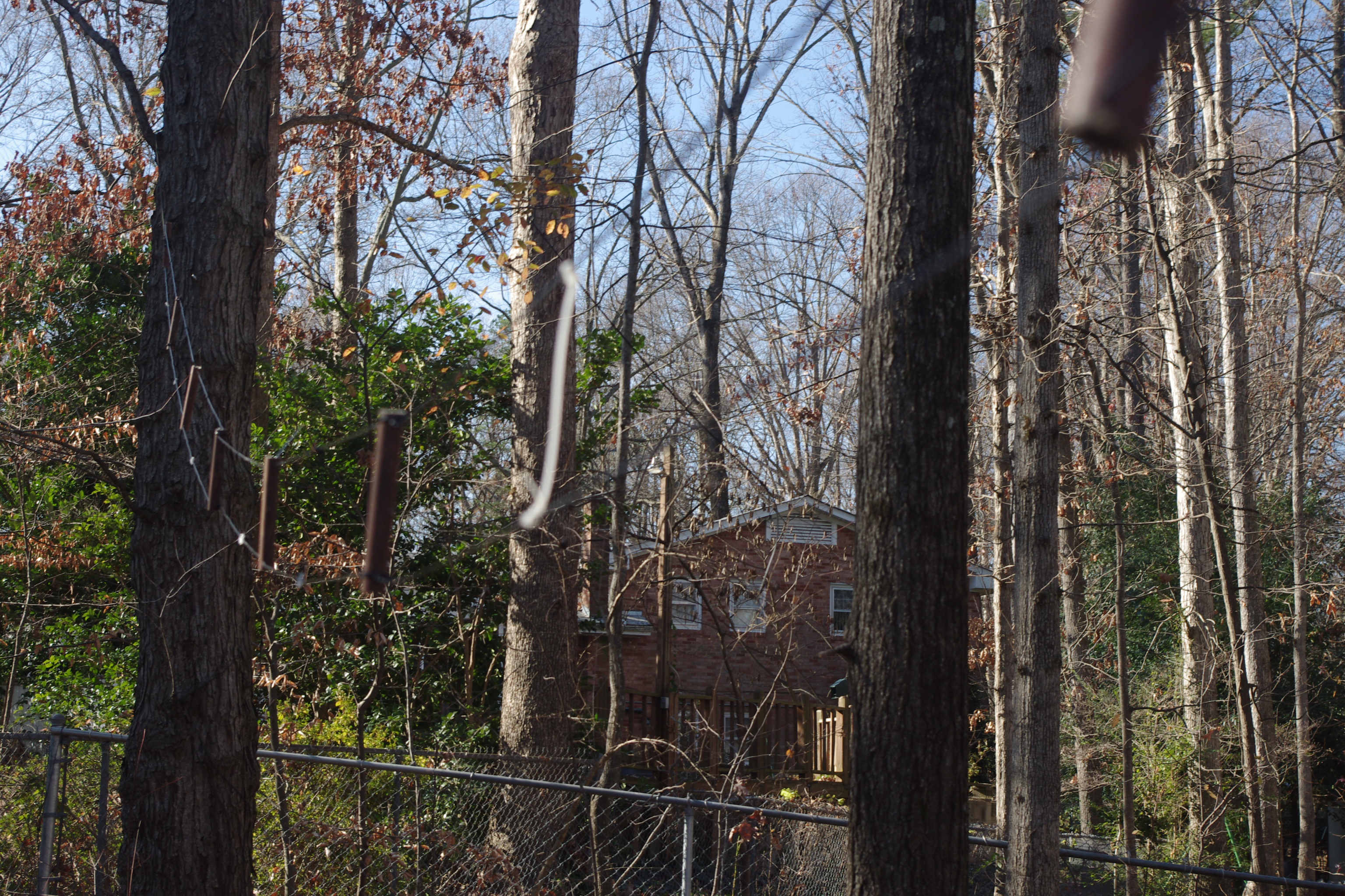
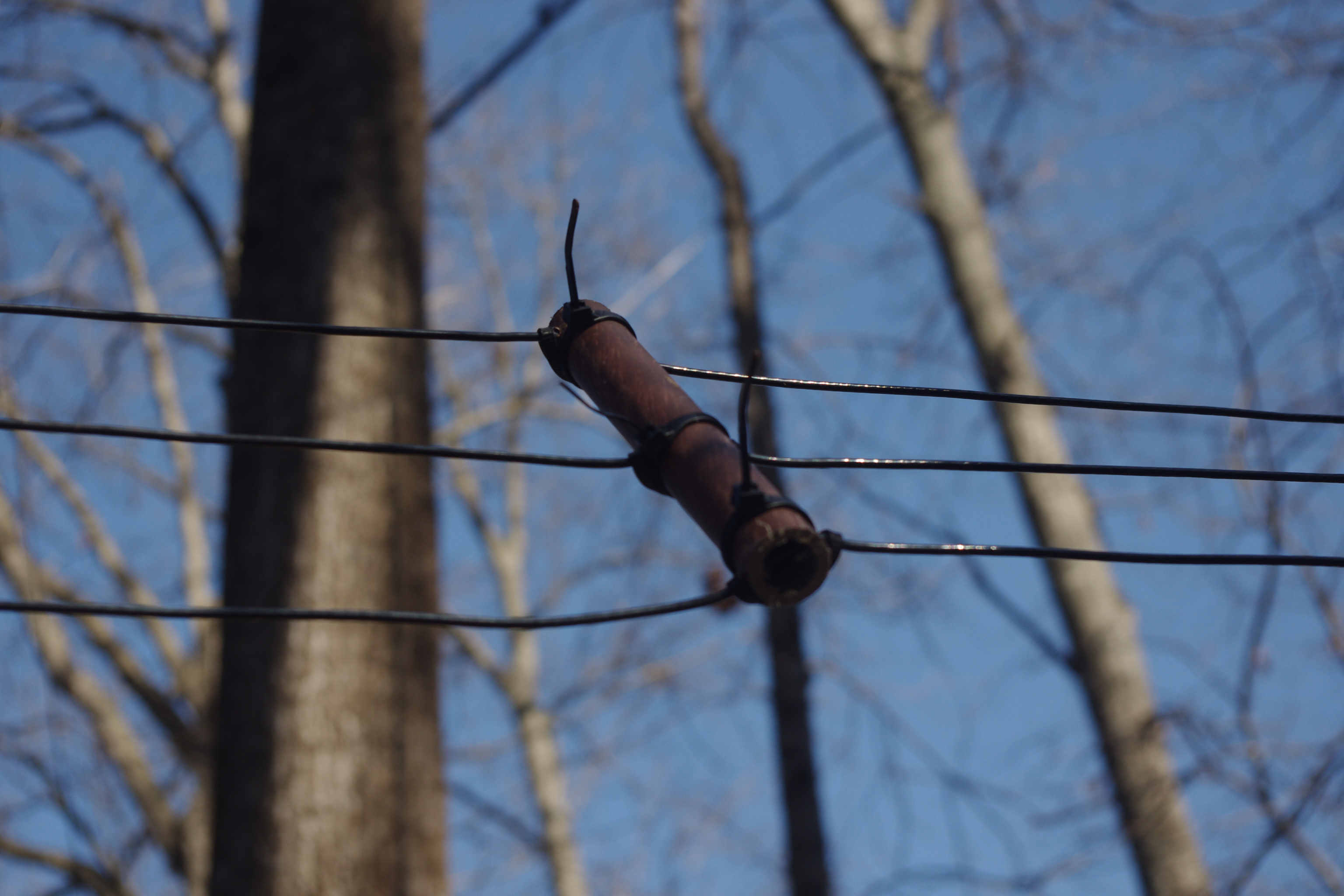
The FCP insulators were cut from an unused piece of PVC electrical conduit. That was also what happened to be at hand in the form of spreaders from an experiment with hex-beams. From the length of PVC available for the job, I cut 16 spacers of 6 inches length(~150mm). Each was drilled through three times, a hole in the center, and one about .5 inches from each end. On the leg with two wires, the spacing is about 5 inches(125mm), while on the leg with three conductors the spacing is only ~2.5 inches(~60mm). The holes are intentionally mis-aligned or drilled at offset angles.   That allows the wire itself to place tension on the spreader to keep the spreaders in place. This method makes it easy to do with an ordinary hand drill – being crooked is an advantage. :)  The mis-alignment alone is not enough to keep the spreaders from sliding, so they are also wrapped with vinyl cable ties as needed. The distance between each spacer works out to about 4 feet(~1.3m). Vinyl cable ties are also used as spacers at the midpoint between each PVC spacer.
Measuring and threading the wire was the most time consuming part of the FCP construction. Because all of the separators are of equal size and drilled the same the side of the FCP with three conductors is more closely spaced than the side with two. This made mechanical construction very easy, the FCP is taut and sturdy, and does not seem to have any adverse effects on basic function.
The transformer and matching network is installed in a nice hamfest/surplus telco box, about 8x8x4. This is a nice weather tight enclosure. The transformer is exact to K2AV specs(by definition – it was wound by K2AV his-self!). The matching network of switched parallel caps is scavenged from the old weather enclosure(a sealed PVC pipe) and re-used in the new junction box. These components fit well enough, but there would not have been space to house the additional toroidal inductor had it been needed.
Besides the apparent signal improvements over the rejected-random-raised-radial-rambling-razzledazzle, the FCP itself has other very practical mechanical merits and advantages over raised radials.
- The folded counterpoise is simple to build.
- The FCP is relatively small, 32′ per side(64′ total length)
- The FCP is a LOT easier to deploy than 30 elevated radials, or burying a dense radial mat
- The FCP lends itself to following contours, and models well when the FCP is not perfectly straight
- The FCP will require a lot less maintenance. The odds of falling branches breaking the FCP here at the home QTH are lower by a factor of 15. (2 legs of FCP vs 30+ radials in 30+ directions, all below branch shedding trees)
- all of the above….. !! yipeee!!
Bottom Line…..
But Kaz, is it equivalent to a full size vertical with a dense mat of radials? Probably not, but there is absolutely zero chance that sort of system can ever be installed at this QTH, so the point is moot.
Do I care? Nope, it “works”, and it “works” better than it’s predecessor 160m antenna systems AT THIS QTH. Very possible/likely that improvement is just a testimony to the poor performance of the prior system. But better is “better”.
Is it snake oil? Probably not, at least not according to the CW skimmer robots, the results K2AV has had with his system, and more important, my own field testing during the CQ160m contest. W8JI has done some comparisons of models. But since they are comparisons to antennas that will not be practical at W4KAZ location, it is academic info. For use here it is about the footprint and 80 foot radials are simply not practical HERE.
2021-03-14 Notation….Nothing Changed
At this point, my only regret is an academic point – not having run the test of inserting the isolation transformer into the old system with the radial-jumble.  The sharp tuning of most 160m antennas suggests that common mode currents will often be a problem as one tunes away from the antenna’s resonance and the reactance increases.   How much benefit is gained from either the isolation transformer or the FCP individually is unknown(to me), but still of both practical and academic interest. I’d really like to know if the old system would have been improved with the isolation transformer installed. Still of interest, but not enough for me to spend time hanging the radials back up again! ;)  Together, the FCP and transformer seem to do a damn fine job here. Certainly the best system that has been active in this location.
What next? FCP phased verticals…..FCP foursquares…..FCP parasitic arrays….. MANY possibilities - if only I had the room to do it.
References:
The K2AV reference page should be used for the most current work by K2AV.
* * *USE DATA FROM HERE:–>https://k2av.com/ * * *
Historical references, related opinions, original subject matter posts, and a few older message threads on the TopBand mail list on pertinent topics:
- Original K2AV NCJ article “The FCP: A 160 Meter Counterpoise for a Postage-Stamp Lot “
- W0UCE’s accumulation of information on K2AV’s 160m ideas, including the FCP
- Photos from W4KAZ FCP install
- Older K2AV discussion of the FCP
- K9YC: “Working 160M From a Small Lot (and Larger Ones Too)”, http://audiosystemsgroup.com/160MPacificon.pdf
- W8JI on FCP, a comparison to antennas that I cannot have.
- Rolling your own FCP isolation transformer, IMPORTANT
- Topband: Where to place a preamp? Switching Beverages?
- Topband: K2AV 160m Folded Counterpoise (FCP), parts and winding for isolation transformer
- Re: Topband: K2AV 160m Folded Counterpoise Antenna (wire suggestions)
- Re: Topband: T-200 vs. T-300
- 2012-05-31, VO1HP FCP install
- Balun Designs commercially available FCP transformer
Other links:
- W1UJ : http://w1uj.net/FCP/
- KY6R : https://ky6r.wordpress.com/2015/04/27/160m-fcp/
- IV3PRK(FCP @ HC1PF) : http://www.iv3prk.it/hc1pf-tx-antenna.htm
- DL0WH : http://dl0wh.de/80m-vertikal-mit-gefaltetem-gegengewicht-nach-k2av/
- DM9EE: http://www.dm9ee.de/FCP_info.html, and http://dm9ee.de/fcp-radials/
- W8TN : https://w8tn.blogspot.com/2012/07/building-k2av-fcp-160-m-antenna.html
- WB5NHL : http://oldcyberdude.com/sample-page/antennas/160m-folded-counterpoise?
- LA9XGA FCP : https://la9xga.com/?cat=54
- M0KWR: http://m0kwr.com/Antennas.html
- AC2RL article in RDXA Fall 2018 (see page 16)
- LA9XGA install: https://la9xga.com/?p=610
- VA3KGS & VA3AC slides on FCP in array
- AC9EZ(pg3 in ACARTS newsletter)
- *
- *
By w4kaz, created on 2012.01.27 at 18:05:45 | last changed on 2012.01.27 at 18:05:45 | Getting the last minute woolgathering in before the contest begins.
Made a last-minute antenna mod to the Inv-L with K2AV FCP. The antenna matching network has been ready for switching out matching capacitors for over a year. The missing piece has been a control box and control cable to the feedpoint. After a bit of consideration of solving this issue before the contest, the brain caught up and realized an interim solution was already in place.
When the Sixpak was added to the antenna system a couple of years back, the existing seven position switch was pressed into ‘temporary’ service as an A/B switch for a pair of 40m dipoles. But they occupy positions 1 & 2 on the switch.
So why not use the other switch positions to serve double duty? The switch is about ten feet from the base of the 160m antenna, so its a short run of control cable versus the 80 run needed back to the shack.
So as a quick and dirty solution, I hacked together a plug to mate to the switch control line. Just plug the 160m switch into the control cable for the seven position switch.
Presto-change-o. Now I can move the best match on 160m from 1820 up to 1845. Sufficient for a CW contest, although 1855 would be ideal. More tweaking needed, but better.
Goals for the weekend are more or less to lay down a good set of spots into the Reverse Beacon Network. No real QSO goals. Try to maximize time spent running, and try to do it over two nights.
C U LÂ Â de w4kaz
By w4kaz, created on 2011.03.31 at 11:57:08 | last changed on 2011.03.31 at 15:52:47 | Wow.
This year was spent at N1LN operating under the NC Contesters Club Call NR3X. The three man team[N4YDU, N1LN, W4KAZ] was a group formed to put N1LN’s station on the air for the contest after failing to find the ops required to run the preferred M/2. I’m sure glad we didn’t let the opportunity slip by – lots of fun.
Propagation conditions were very good for this contest – the best I have caught in several years. Improved conditions and lots of active stations made the bands wall-to-wall donald duck essessbeee chaos. Very difficult to copy weak stations, but there were lots of LOUD signals too. Heard many layers of QSOs on the same frequency.
Lots of little fun facts trickled in during the course of the weekend. Made the mistake of trying to switch from 15m to 20m too early – and lost a high rate run. Lesson: Next time listen to N4YDU! Made the mistake of giving up too easily on “terrible” high QRM run frequencies. Lesson: Don’t move before the rate plummets! Beast it like N4YDU!
This contest, I made it a point to move the antennas around more often when the rates slowed and was rewarded with small boosts in the rate several times. Still not enough experience to know when to look for openings in directions other than EU, but sliding the beams 20 degrees either side of directly at Central EU usually found a few new ones hiding in the favored directions.
Getting the most out of N1LN’s station is something that is seeping in slowly. The options in a station designed for M/2 competition are quite a bit more complex than just putting the butt-in-chair. Also a world of difference between good yagi’s and dipole draped through the trees.
Looking at the raw score[3830 blurb] and the CQ WPX results database, we would have the fifth highest score ever posted for a Multi-One from the USA – based on scores through 2010. Unfortunately…. at least four other stations posted higher scores than our own for WPX SSB 2011, including what will be a new US record. So instead of making it into the top 10 all time scores, we might just wind up in the top 20. There are several score in the ballpark of our 11.7m, so it will depend a lot on how clean our log checks out to see where we land. There are going to be a LOT of great scores from this year’s contest.
We began the contest with general goals of 3000 to 3500 Q’s and at least 1000 mults. We thought the improving conditions would help, and thought the mults would be the more difficult goal to reach. Recent rule changes to Multi-Single for WX allow for 10 “band changes” per clock hour with one transmitted signal on the air rather than a mult radio. This allows only 5 mults on different bands, assuming the run station remains on a single band for the duration of a clock hour. That made for a lot of difficulty working mults on the second radio without disrupting the run station and losing a run frequency. So the final result is a really good showing, and very happy with the mult totals.
A lot of the mults, as well as a lot of widespread DX called into our runs. At the N1LN station, I tend to get caught off guard by the variety. While running I logged B7, HS, several ZL and VK stations, all with the antennas pointed in directions not favorable for those directions. It is really fun operating at N1LN.
Like always, an hour after my last shift my thought run towards “Why did we do this?”. The next morning, after a solid night’s sleep the question morphs into “It really wasn’t THAT bad, was it?”. Less than a week later, the question again morphs, becoming “When can we do that again?!?!”.
The Band conditions were a whole new can of worms compared to recent years. It is time to re-make the “rule book” to be dynamic enough to fit the changing conditions. What worked as band strategies for periods of crappy propagation do not apply to periods of good propagation. Go where the rate is – but where the heck is that gonna be?
160m – no activity, high storm noise.
80m. There was a moderately high noise level on 80m, but the nice beverages at N1LN’s station compensated. During the night shift 40m dropped off due to the heavy QRM, and lack of EU calls while trying to listen split. Better to work 1 pointers than nothing, so down to 80m we go. 80m was crowded, but not nearly the QRM levels of 20m and 15m. Decent rates running strings of US stations with a nice mix of North and Central Europe stations calling every 4th or 5th Q. With the beverage pointing at EU, the 6 and 7 land US stations were hard to copy, so the beverage controls got a decent workout switching from W to NE. That run held up through the whole shift.
40m. Just not any fun operating 40m on SSB. Split didn’t pan out. Ugh.
20m was good – if you consider slam packed high QRM condx good. Even with the QRM, there were bright spots when strings of strong stations would call in. Mostly 20m was neglected in favor of the 15m bonanza. It sure seemed like rates were low because of the good 15m conditions.
15m was wide open on Sunday. After Saturday, we were thinking we were heavy on 15m, and might need to press 20m harder to keep the rate up, but N4YDU was being called by multiple stations. Asking for fills was common due to crowded band conditions. But it was great to hear 15m hopping again. Probably the best 15m conditions I’ve operated, and certainly the best I’ve seen yet from a top-notch station.
10m – Finally! Friday evening started with a 10m opening to ZL/VK territory, which may have been lost opportunities. Not much activity on 10 on Saturday. Sunday afternoon the bubble burst on 10m. With the antennas pointed south N1LN and YDU were able to run stations for a short period, and we were getting hits from all directions. One of the better gems was a call from a station in Malta. YDU indicated it was probably a Caribbean skewed skip opening, but it was sustained for the better part of an hour and accounted for the bulk of the 10m Q’s logged.
The Good: The generosity of N1LN and N1YXU in hosting the operations is deeply appreciated. Great working with N1LN and N4YDU.
The Bad: Too easy to bail on high QRM run frequencies. The joke was that was the GOOD run frequency.
The fUgly: Murphy was off visiting others. Maybe he was happy with having smoked the home QTH microwave on Thursday. [Blown microwave oven magnetrons smell just like blown power supplies.]
Raw Score [3830 blurb]:
Call: NR3X     ****    Operator(s): N4YDU, W4KAZ, N1LN   ****  Station: N1LN

Class: M/S HP   ****    QTH: NC                             ****  Operating Time (hrs): 48

Summary:
 Band  QSOs
------------
  160:    1
   80:  334
   40:  695
   20: 1013
   15: 1203
   10:  234
------------
Total: 3480  Prefixes = 1267  Total Score = 11,738,755
**
By w4kaz, created on 2010.10.05 at 05:54:37 | last changed on 2010.10.05 at 08:28:53 | Spent some time over the last week re-conditioning an old Mosley TA-33 jr, courtesy of N4YDU. The date on the box is 1979. Gotta wonder if 30 year old aluminum is ready for metal fatigue, but its a novelty project. Some of the hardware was shot, so I decided to replace most of the u-bolts. Got a quote from Mosley on those parts, but since I needed some other hardware bits for other projects, I instead went with parts from DX Engineering. The u-bolts available from DX engineering were slightly shorter than the original parts, but seem to be a good fit. Spent some time cleaning everything up, and used a scotchbrite pad to remove some of the oxidation and crud around the joints and at the trap connections. Got all of the elements assembled on Friday evening without burning any of the chicken on the grill.
That project will likely languish after testing the elements for resonance. Might assemble the whole shebang for an on the ground SWR check, but it looks like some moderately serious tree trimming would be required before it could ever actually be put to use at the QTH. More likely to use it for Field Day. The TA-33jr is a versatile bit of kit. It is light weight for a three element yagi. If space or weight were a problem the driven element and reflector can be used to make a ta-32jr, the two element version. The driven element can also be used by itself as a stand alone dipole. Mosley also sells a set of traps for converting the low power version into the hybrid light weight/high power version.
Saturday morning was spent over at KZ1X tugging on ropes along with KA1ARB, with KZ1X and N1LN up the tower. Steve needed to debug a problem with his 20/15/10 yagi. We found that the coax run up the tower seemed to be the problem. After swapping that off to a different coax run, things looked better. Steve also hung a replacement 80m dipole for one that went down with a falling branch. Got a first look at the K3 panadapter while doing the in shack checks. A cool gizmo.Â
Lesson Re-Iterated: Do NOT trust readings from an MFJ antenna analyzer when the power supply is weak. A portable supply or external battery pack is worth using when that is practical. My own MFJ-259 has long had its internal battery pack removed in favor of an external pack. The pack is about 1″x3″x”slightly longer than the 259″.   It’s a cool little pack, that has a charger and two output jacks. It is taped to the back of the MFJ-259. With 10 rechargeable batteries it supplies about 13v when fully charged. It is slow to charge, but the cigarette lighter socket makes it versatile. Note: don’t have the matching solar cell, just the charger, ac supply, and car adapter.
Had a bit of R&R on Saturday unwisely spent watching the LSU-Tennessee game. Being an LSU football fan is an interesting experience - but not always pleasant. O’course, the Tennessee fans really got the short end of the stick, but their own teams last second decisions were just as squirrelly as those of “The Hat” and associates. I sure hope LSU gets their offense to pull together going into the tough part of their schedule against three current top-20 teams(Florida, Auburn, Alabama) in the next four weeks and end the season with another(Arkansas). Ouch. Tough schedule. Life in the SEC West.
Glad to see the Tigers defense is working well as a unit, but the talent on the offensive side is there too, just not clicking yet. After being beaten by Tennessee(and UNC and WV) right up to the brain death of coaching staffs on both teams on the last play of the game, they really need to find their best game quick. Otherwise the losses will accrue rapidly, despite excellent defensive play. I suppose Florida will be mad as hell after their spanking in Tuscaloosa.
Sunday R&R consisted of a hour or two in the shack. Turned on the radios and heard some of the California QSOP guys on 15m. I’ve sorely missed 15m these past few years, so it was a bit of fun to make a few Q’s on the band. Signal strengths ranged from S1 to a very loud S9+, and only one station was called without answer. That’s an improvement compared to 15m over the past two years. Not a lot of stations heard, but a few European QSO’s were also decent copy. 10m was still silent.
Requests for audio reports indicated the RFI issue introduced on SSB when setting up the sound card DVK into the SO2R set up is now fixed. [Yippeee!] Good audio reported by all. The issue with the RFI on the PTT line for the K2 is still a mystery, but ferrites on the mike and PTT lines going into the K2 were needed to resolve the problem.  Resolving that problem has me looking forward to the coming contest season, and hoping that the bands are better during 2010 Sweepstakes.
As fall rolls in it is time for some much delayed antenna maintenance on the 160m inverted L. It would be nice to get the 80m element added, and the radials need maintenance since the falling branches have taken out about half of them since last contest season. Gotta work that into the leaf raking schedule – the sooner the better.
By w4kaz, created on 2010.09.26 at 06:09:23 | last changed on 2010.09.26 at 14:21:35 | I’ve been running a bit of an informal experiment in house lighting for the past seven or eight years. Been using CFL’s since they first appeared in the local retail outlets. Hate to think about how expensive they were before they became Politically Correctified.
Some of the fixtures in the hacienda have sockets for two bulbs. I’ve gradually been removing the old bulbs and replacing them(simultaneously) with a mixed pair – a regular incandescent paired with a “name brand” compact fluorescent. Just wondering if the CFL longevity claims have any merit.
The sample size is pretty small, but the CFL performance has been a lot less than the hype. I had high hopes for one of the outdoor fixtures, but the outdoors CFL crapped out before the incandescent. The CFL crapped out first in one of the indoor fixtures too.
CFL Bad: The bad points
- Long life claims not meeting expectations
- Seem to be “bug magnets” when used alone, much more so than incandescents. Â The insects must love the color of the light, because the bulbs run a lot cooler than incandescents. Â This is a big problem outdoors. Â This is not as noticeable a problem when combined with an incandescent.
- Light color distasteful to certain humans. Â (can also a good point-very subjective)
CFL Good:
- The CFL bulbs use less energy. Â In hindsight, I’d like to test this claim too.
- Price per bulb dropped to more reasonable levels, but the shorter than hyped useful bulb-life offsets this benefit.
- Light color is improved by pairing with an incandescent of similar luminescence.  Combined, this makes for improved work area lighting.
I also had high hopes for the longevity claims – hopes were shattered by the reality. Don’t see any improvements in either longevity or the light color with newer bulbs. Wondering what the cause for the “early” failures might be. Is it:
- situational, something about the location?
- indoor vs outdoor(slightly better life indoors)?
- voltage spikes?
- current spikes?
Whatever the reason, the CFL’s are moving rapidly to the top of the “get rid of this crap” list. Several reasons, besides the shorter than advertised bulb life. Don’t much care for the light color when they are the only source.
The color can also be a positive side to the CFL’s – if you like it.  It seems worthwhile  to combine a CFL and an incandescent for workshop lighting, the two together are good.
Conclusion: In general, for my purposes, CFL’s suck. The CFL’s absolutely suck for outdoor usages. CFL’s really suck most in the winter outdoors. They seem to be good for about half there rated output once temps drop into the 50’s.
Time for the LED’s from Lighting Science Group. Â Getting close to pulling the trigger.
By w4kaz, created on 2010.04.15 at 04:15:58 | last changed on 2010.05.03 at 09:28:06 | Chasing down the RFI caused by inserting all of the home-brewed SO2R components into the station set up was a useful hands-on experiment. Annoying, but certainly educational. I verged on ordering the ARRL RFI tome, but now the thing is fixed, owning the reference seems less urgent. Might be worth reading though…..probably quicker than re-inventing each technique personally.
To start, the shack layout resulted in a few less than ideal situations. Both radios are side-by-side, separated by about 300mm. The computer that logs and controls both radios is on a rolling cart normally kept close to the station desk. The computer was also being introduced into the audio chain as the DVK, and I was also working towards routing the mic audio through the sound card full time. The cramped space on the desk is further reduced by the antenna switching controls and an antenna tuner. One set of bandpass filters is built into a relatively large computer case, and that occupies much of the top shelf.
No RF problems were noticed on CW, but on SSB the audio was terrible, and I got many reports to that effect. Apologies to those who were exposed to it.
The unshielded plastic enclosures used may have contributed to the problem, but so far most of the trouble has been corrected by applying the normal RFI kludge, clamp on ferrites. Shielded enclosures probably can’t make the problem any WORSE though.
The audio stream for the Yaesu FT-920 was relatively easy to clear up. Three or four turns of cable through one or two ferrites seemed to do the trick. The K2 was more difficult to tame, but it was also the furthest from the computer. I expect that the longer audio cables needed to reach the K2 made better antennas for picking up the stray RF. The cables used are a mix of CAT-5 and shielded RCA audio cables. The CAT-5 cables carried the mic audio, PTT and CW from the So2R box to either radio.
In addition to the ferrites, I also routed the audio from the computer through an isolation transformer. That step alone almost completely solved issues with the FT-920. Using a separate power supply for the SO2R box resulted in acceptable audio - better, but not BEST.
Two of the issues were a big surprise – and I only discovered them as RFI ingress points because I reached the point where I was determined to cover every base. The separate power supply was an issue that was unexpected, but should not have been. NT4D has made that point to me several times over the years. Unfortunately good advice often falls on deaf ears. I have heard the gospel now….
The one that I really dd not expect was that the PTT line might be an RFI source. It became obvious this was a source when I methodically disconnected various cables on the K2 end of the chain. Low and behold, once the PTT line was disconnected from the SO2R box – no more RFI.
I may now re-visit the entire chain, substituting a better quality cable to see if there is any difference or if fewer ferrites might be required. It took three ferrites with about five turns on each to subdue the RFI ingress from the PTT line.
Here’s a summary of the mitigation steps taken to end the RFI issues.
Problem #1:
Power supply – One source of RFI problems was sharing the radio power supply with the SO2R box. Putting the SO2R box on a separate wall wart helped a lot.
Problem #2:
SO2R box cabling. Because of the shack layout, the SO2R cables are all pretty long. Putting ferrites on all cables more or less solved the problem with the FT-920. Still had RFI on the K2.
Problem #3:
Added .01 bypass caps across all of the relay coils and DC connections in all switch boxes.
Problem #4:
Didn’t really have ferrites on ALL of the cables. I really didn’t expect the PTT line to be an RFI issue, but solving the RFI problem on the K2 required ferrites on both ends of the PTT line(at the radio mike jack, and at the relay output in the SO2R box), as well as on the foot switch itself(at the SO2R box). While I was at it I added ferrites to the DC power cords too. It took three ferrites right at the mike jack on the radio end, so that may have been the real source of ingress.
Problem #5: Add isolation transformer in line with audio from the computer before going into the SO2R box. Putting the transformer at the input to the SO2R box was an arbitrary choice – I don’t know if its location in the audio stream is of great consequence in mitigating the RFI. Its placement there ensured only one transformer was required, since all audio is routed through that location, not being split until later in the SO2R box. The location was convenient – perhaps not ideal.
Caveat: It is possible I also did something else inadvertently which helped solve the problem, but after a couple of weeks of head scratching and trial and error, I can say that UNdoing any one of #1 thru #5 will re-introduce some amount of RFI.
The problem with the PTT line really has me perplexed, but I guess it is in close proximity to the audio cable at the radio mike jack, so any RF on the PTT line is probably getting into the audio there.
After all of the trial and error, my impulse in the future will be to add ferrites on all control cables on both ends, and immediately after they enter/exit each device.
By w4kaz, created on 2010.03.03 at 20:54:49 | last changed on 2021.05.06 at 21:12:35 | Leave it to the RedmondGeeks to create a useful tool but leave it undocumented rather than make it easily available. And a big thanks to NumberOneSon for showing me the trick.
There’s a feature for Windows 7 users called GodMode, which is simply a tool/folder that has a lot of the more useful system administration tasks grouped together in one place. [As opposed to navigating five screens to get to them.]
All that is required to use the feature is to create a folder then re-name it. See the link for the details or just goog up the word “godmode” for yourself. No use re-inventing the wheel here.
[hey! I didn’t name it…]
By w4kaz, created on 2010.03.01 at 06:44:19 | last changed on 2015.07.12 at 21:38:31 | OBSOLETE:Â Versions after version 11 are much better. Â Disregard if using a version of Writelog after 2011. [w4kaz, 20150101]
ENVIRONMENT: The following applies to an install of Writelog on a Windows 7 64 bit platform with User Account Control enabled. Probably works for any Windows 7 version. It may also apply to Vista, but that version of Windows has not found its way into my hands, so experiment at your own speed. All installs were done under the administrators account, and testing of the application done in a limited user account. No special permissions were granted to the limited user, nor to any of the directories.
BACKGROUND: The new BlogBox is not used down in the KazShack dungeon, but is the day-to-day computer. After a contest, I move the log file up to the main computer and use an install of WriteLog on that box to spew out the Cabrillo, and ADIF backup, and the reports. For my own nefarious reasons, I chose to set the new BlogBox up with an administrative user, and do all of the day-to-day activities within a limited user account.
WriteLog is still backwards compatible with older versions of windows, and runs well even on systems with limited resources. That is something that is a useful feature, as it allows a wide choice of hardware platforms to be pressed into service. Plus, I just damn well like WriteLog better than anything else.
But since Writelog was designed before the day of user accounts there are some adjustments that need to be made to get it working in Windows 7.
THE INSTALL: One approach used by many is to disable User Account Control[UAC] and run the system as the administrator. That’s a judgment call. Diametrically opposed to the goal here…but used with success by many.
Another approach that seemed to work is to install it under an account with administrator privileges. But that also falls short of the goal, which is to get it going under a limited user account. When installed as the administrator, the user accounts were able to run the program, but not able to save the configuration settings.
The approach that seemed to work is to install WriteLog into its own directory[I named it c:\writelog_install_home].
The install went without a hitch. The real trick is simply to find where everything is right after the install. The important part is locating the “writelog.ini” configuration file. For whatever reason the RedmondGeeks in Windows 7 [and maybe Vista] have an environment variable [“appdata”] that is used for hiding certain bits of data under UAC. The term “hiding” is used deliberately since the directory referenced by the environment variable is indeed hidden.
Finding STUFF:
- start a command prompt window, and type “set” with no other parameters. that will display all of the environment variables. The pertinent one is “appdata”
- In the file explorer, under “organize” –> “Folder and search options” –> “View” -> “Hidden files and folder” check “Show files, folders and drives”
- In Windows 7 user info/program data is generally is stored in “C:\users\xxxxxx”, where xxxxxx is whatever your user name might be.
- Writelog creates a directory in the “c:\users\xxxxxx\documents” directory[i.e., “My Documents” under the logged on user account] for its data files, wav files, contest “ini” files, etc.
The basic install is all pretty easy once you locate the files. The critical file is the configuration file, “writelog.ini”. In this sort of install there are actually two copies of writelog.ini. One copy is in C:\windows. That copy is an abbreviated version, which has what I expect are the bare minimum bits of info required by WriteLog to run. [NOTE:After installing the program several times it is possible this copy in C:\windows could just be cruft left in place from a previous install.] It seems likely that “writelog.ini” is used to initialize the program. Probably best to ignore that copy of Writelog.ini, and leave it undisturbed. You will need to have admin privileges to edit it.
The second copy is stored under the c:\users\xxxxxx\appdata directory in the sub directory \VirtualStore\Windows. The full path in my install was “c:\users\w4kaz\appdata\VirtualStore\Windows\writelog.ini”. THIS is the file used to store config settings for the logged on user, and it is here that customizations should be added.
The user copy is created for each user individually and uniquely. That copy is the version that can be customized as required for the particular situation. A lot of WriteLog users have custom versions of their config file for different situations. Rather than maintain numerous copies of the file, it might also be appropriate to define a separate user for each situation. Then all of the copying/management of config files could be avoided by simply logging on to the appropriate user.
That’s enough to get the program functional as far as opening logs, exporting reports and files. Testing connectivity is to peripherals is more difficult, since the shack is not in the same location and there are no USB dongles yet in use in the KazShack.
The defaulted directories were as follows, after the user had opened the program, and done a “save config”:
[Install]
Directory=C:\Program Files (x86)\WriteLog\
[Configuration]
WaveFileLocation=C:\Users\w4kaz\Documents\WriteLog\WaveFiles\
RecordingLocation=C:\Users\w4kaz\Documents\WriteLog\AudioRecording\
DataFiles=C:\Users\w4kaz\Documents\WriteLog
[Multipliers]
Location=C:\WriteLog_install_home\Programs\
Wave files and data files are defaulted to the user’s documents folder. Customize those as needed.
The only real curiosity is that the user writelog.ini install directory was not updated in the final install to reflect the actual install directory. Its probably best to update that entry to reflect the actual installation directory.
Installed in this manner I have not yet run into anything that required administrator privileges, or that Writelog be “run as administrator”. But admittedly, I have not yet tested keying CW, .wav file audio, or rig control. The BlogBox is not the computer used for contest logging, nor do I use any USB dongles at this point. In the end, admin privileges may indeed be required for full featured usage that bangs away on the com ports, but in a limited use it is not required. Best guess is that LPT keying probably is more complicated, if possible at all, and that a Winkeyer would probably work easily via USB.
CAVEAT: After I was satisfied the main program was functional, I went through the Writelog directory and executed each of the utility programs. The “tuning indicator and audio snapshot” program received an error window trying to edit the system registry. That program is for use with RTTY, a mode I am not using, so it is not clear to me that the program has actually failed. After acknowledging the error, the program appears to load and be ready for action.
UPGRADES: For these tests, Writelog v10.70c was used for the full install. Upgrades 10.71 through 10.75 were then applied via the administrator, with no problems encountered. The program ran for both the administrator and the limited user accounts.
And dats da fax, jack…..
By w4kaz, created on 2010.01.31 at 13:19:21 | last changed on 2010.01.31 at 13:29:34 | After building the 80m/160m splitter, it seemed like the signal levels from the K9AY were down a bit, probably from losses in the filters. So after looking around at pre-amps, and procrastinating on buying the Ar2 preamp, I again landed on the W7IUV site.
W7IUV has updated his preamp schematic, and it looked easy enough. Building the project was simple after gathering some suitable parts.
Trying the pre-amp out seemed to show that it was more or less filling the desired role quite well. With the preamp engaged, levels from the K9AY were now on par with signal levels from the transmit antennas on both 160m and 80m. The preamp is installed in the shack just ahead of the band splitter.  Noise levels on the RX system were down about two to three S units from the TX antenna in these moderate noise conditions.
During the 160m contest this weekend, the RX system got its chance to proove itself. Noise levels here were moderate – not as quiet as good winter conditions, but not S9+ summertime noise either. The RX antenna with the preamp turned on was always the best choice on weak signals in these conditions. It also necessary to switch the K9AY around a lot – signals were not always best in the expected direction because of higher noise to the north.  The southeast direction was dead quiet, but from here in central NC there isn’t much to listen to on 160m to the SSE. The actual compass direction on the SE leg is about 10 degrees south of southeast.
So the short version is that the preamp is an improvement when splitting the RX antenna for two radios. Â
Future projects/curiosities:
- Try moving the preamp out to the base of the K9AY, probably in a new K9AY switch box
- Test the RX with the splitter removed, preamp on/off.
Â
By w4kaz, created on 2009.12.19 at 04:09:20 | last changed on 2009.12.18 at 11:33:43 | Finally figured out what to do with burnt out strands of Christmas lights. Scavenged about 100 ft of wire in 20-25 foot long hunks and used it to augment the radial system on the K9AY.
The K9AY RX antenna itself is in need of replacement. It is constructed of 18ga wire, and has had several breaks in the past couple of years. Right now it has five or six splices where repairs were made. Probably time to replace it with 14ga THHN, now that copper prices are down again. A 500ft spool of 14ga stranded THHN housing wire was $35.00USD yesterday at the local BigBox retailer.
Time to stockpile before hyperinflation kicks in?
|
|
